EDIT PAGE - Introduction
EDIT PAGE
Omnisphere’s EDIT page has been designed to
provide a useful set of controls over every aspect of the sound, but in cases
when more precise and detailed controls are needed, the Zoom feature reveals a
set of deeper controls. You can
also think of the EDIT page as an “Overview” of the sound.
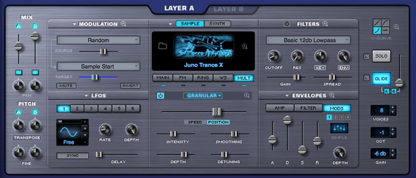
The EDIT page is divided into two primary
sections, Common & Layer. The
Patch Common parameters on the far left and far right of the EDIT page are
controls that affect the whole Patch (both Layer A & Layer B). All of the Layer-specific parameters
are in the large middle area, and are generally unique to the Layer. This middle area controls change when
Layer A or B is selected. The
common controls on the left and right sides do not.
EDIT PAGE - Introduction
EDIT PAGE - Introduction
Omnisphere’s EDIT page has been designed to
provide a useful set of controls over every aspect of the sound, but in cases
when more precise and detailed controls are needed, the Zoom feature reveals a
set of deeper controls. You can
also think of the EDIT page as an “Overview” of the sound.
The EDIT page is divided into two primary
sections, Common & Layer. The
Patch Common parameters on the far left and far right of the EDIT page are
controls that affect the whole Patch (both Layer A & Layer B). All of the Layer-specific parameters
are in the large middle area, and are generally unique to the Layer. This middle area controls change when
Layer A or B is selected. The
common controls on the left and right sides do not.
EDIT PAGE - Common Controls
EDIT PAGE - Common Controls
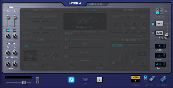
The Patch Common parameters in the Footer and on the far left and far right of the EDIT page are controls that affect the whole Patch (both Layer A & Layer B).
All Layer-specific parameters are found in the large middle area, and are generally unique to the Layer.
When you change the view to a different Layer, the controls in the middle area will change to reflect the settings in the selected Layer. The common controls in the Footer and on the left and right sides will not change, as they are common to both Layers.
The Patch Common controls on the left include the MIX section, with Level, Pan & Pitch controls. Patch Common controls on the right are the Velocity Curves, Solo/Glide modes and Voice controls. The V-Curve (Velocity Curve) section also has a Zoom option for customizing Velocity curves.

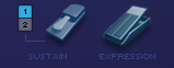
The Footer contains a Part level fader, a Part level meter and Mute/Solo buttons that mirror those found on the MIXER Page. The Footer also contains Layer Selection Buttons, a Link Layers button, Latch Mode button, Trigger Mode controls, Sustain Mode selection buttons and Sustain and Expression pedal switches.
There are other parameters that are common to the whole patch as well. The LFOs are common, as are the Modulation Envelopes.
The general rule to follow is; “If it’s a numbered parameter, it’s a control that’s common to the whole Patch”.
NOTE: Many of the parameters found in the Common Controls areas of the EDIT page can also be found on the MAIN page.
EDIT PAGE - Selecting & Linking Layers
EDIT PAGE - Selecting & Linking Layers


The Layer Selection Tabs & Buttons toggle between the controls for each Layer in a Patch. The parameters in the center section of the EDIT page will change when toggling between Layers. The common parameters in the Footer and on the far left and far right will not change when switching Layers.
The Layer selection controls will highlight to indicate the selected Layer.
NOTE: The Layer Selection Buttons in the Footer will remain visible when the Soundsource Browser is open. You can use the Layer Selection Buttons to toggle between Layers while browsing Soundsources, which makes it very convenient to quickly load or replace Soundsources for both Layers.
Linking Layers
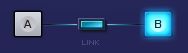
The LINK Button makes it possible to lock the controls of both Layers together. When enabled, any parameter changes made in one Layer will be exactly mirrored in the other.
The LINK Button will highlight when enabled, to indicate that the Layers are linked.
When the LINK Button is disabled, changes made to Layer parameters will only affect the selected Layer.
For example, if you select Layer A and enable the Link Button, moving the Timbre slider on Layer A to the far left will cause the Timbre slider on Layer B to also move to the far left.
NOTE: Layer On/Off, Pan, Level, Transpose, Coarse Pitch and Fine Pitch are not linked when linking layers.
EDIT PAGE - Latch & Trigger Modes
EDIT PAGE - Latch & Trigger Modes

Latch & Trigger Modes
The Latch Mode and Trigger Mode features extend the performance capabilities of Omnisphere, especially when used together with Live Mode or Stack Mode.
Used together, they enable a wide range of creative performance, live remixing, and composition techniques to discover and explore.
NOTE: Be sure to check out the “Latch and Trigger Modes” tutorial, and the in-depth sections of the Reference Guide for using Latch & Trigger modes together with Live Mode and Stack Mode.
Latch Mode

The Latch Mode button allows you to toggle Latch Mode on or off for the selected Part.
Selecting the Latch Mode button will enable Latch Mode. The button is highlighted when Latch Mode is enabled for the Part.
If you are already holding sustained notes when you enable Latch Mode, those notes will be latched.
Selecting the Latch Mode button again will disable Latch Mode for the part.
NOTE: Disabling Latch Mode for a Part while it’s playing will immediately send an “All Notes Off” message to the Part. The tails from FX and release stages from envelopes will continue to decay. The "All Notes Off" message applies only to notes playing on that Part.
NOTE: A Part’s Latch Mode status can also be viewed or changed from the LIVE MODE or STACK MODE pages.
Trigger Mode

Trigger Mode enables real-time quantization of incoming MIDI notes, so that Parts will always play in sync. This makes it very easy to experiment and improvise along with other clocked sources without losing synchronization. These features are a lot of fun to use for jamming and building up ideas quickly!
The Trigger Mode icon displays the current Trigger Mode for the selected Part, and allows you to access the Trigger Mode menu for that Part.
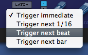
To change Trigger Modes, select the Trigger Mode icon and choose the desired Trigger Mode from drop-down menu. A checkmark will appear next to the selected option, and the Trigger Mode icon will change to reflect the selected Trigger Mode.
Trigger Modes
Immediate: This is the default Trigger Mode. MIDI input is not quantized, and playback of MIDI notes is immediate.
Next 16th: this option delays the playback of incoming MIDI notes to the next 16th note. In other words, notes are quantized in real time to the next 16th note. If you play ahead of the next 16th, there may be a slight delay before the note sounds. This delay will be a maximum of a 16th note at the current tempo. This mode makes it easy to play quick phrases in perfect sync with other Parts or clocked sources.
Next Beat: this option delays playback to the next beat. If incoming MIDI notes arrive ahead of the next beat, the delay is a maximum of one beat. Next Beat mode makes it very easy to trigger rhythmic patches in perfect sync, and when used together with Latch Mode, for layering phrases that are quantized to the beat in real time.
Next Bar: delays playback until the next bar. If MIDI messages arrive ahead of the next bar, the delay is a maximum of one bar. This mode is especially useful if you want to synchronize phrases on the downbeat of a measure. You can press a note anytime in the previous bar and it will wait until the next bar to play.
NOTE: The selected Trigger Mode also affects a Part’s Arpeggiator, LFOs and Envelopes. These will also be delayed until the note itself is triggered.
NOTE: A Part’s Trigger Mode can also be viewed or changed from the LIVE MODE or STACK MODE pages.
EDIT PAGE - Sustain & Expression
EDIT PAGE - Sustain & Expression
Sustain Modes

There are two Sustain modes available in the Footer, Standard Sustain (Mode 1) and Alternate Sustain (Mode 2). The Sustain Mode selection switches (numbered 1 and 2) allow you to switch between modes, and are MIDI-learnable switches.
Standard Sustain (Mode 1)
When the Standard Sustain Mode is selected, using your Sustain pedal will behave like a normal Sustain function. Notes played then released will be sustained, and additional notes played will overlap and sustain. Sustains will be heard until the sound decays or the pedal is released.
Alternate Sustain (Mode 2)
When the Alternate Sustain Mode is selected, when your Sustain pedal is pressed, notes played then released will sustain as normal, but additional notes played will cut off the previously played notes. This is especially useful when playing Rock style bass lines, and is great for certain chorded phrases as well.
The last notes played will continue to sustain until the sound decays or the pedal is released.
NOTE: Notes that are still held when playing additional notes won’t be cut off. If you play and hold a note, then play another note, both will be heard and sustained.
Sustain Pedal Icon

The Sustain Pedal Icon is an on/off toggle. It defaults to on (enabled). When this switch is enabled, the Sustain pedal will always affect Sustain (CC#64).
When this switch is disabled, the Sustain pedal will still send CC#64 messages, but will not be applied to Sustain. This allows the Sustain pedal to be used exclusively for modulating other parameters using the Mod Matrix, or by MIDI-learning controls such as on/off switches for FX modules, or Layer on/off controls.
NOTE: When the Sustain Icon is enabled, the Sustain pedal can still be used to modulate or control other parameters, however those additions will act in combination with the Sustain function.
Expression Pedal Icon

The Expression Pedal Icon is an on/off toggle. It defaults to on (enabled). When this switch is enabled, the Expression pedal will always affect Expression (CC#11).
When this switch is disabled, the Expression pedal will still send CC#11 messages, but will not be applied to Expression. This allows the Expression pedal to be used exclusively for modulating other parameters using the Mod Matrix, or by MIDI-learning controls such as FX or Filter parameters, or Layer mix controls.
NOTE: When the Expression Icon is enabled, the Expression pedal can still be used to modulate or control other parameters, however those additions will act in combination with the normal Expression function.
EDIT PAGE - Layer Mixer
EDIT PAGE - Layer Mixer
The MIX section offers controls for the levels and panning of Layer A and Layer B.
LAYER MIXER LEVELS
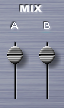
The level sliders are used to blend the two
layers, oftentimes, even a subtle change in level can make the patch sound very
different.
The Layer mixer level sliders cover
a range of -inf dB (silence) to +9.54dB.
To quickly set the Level to 0dB
(unity gain), select the slider when holding down the Command key (Mac) or
Control key (Windows). It will
snap to the 0dB Unity gain position.
Range -inf dB (silence) to +9.54dB
LAYER ON/OFF

Below each of the Layer Mix sliders are two
on/off buttons that determine if a Layer is active or not. They also can be used to mute either layer
to make comparisons without having to adjust the Layer Mix faders. If the button is light blue, the layer
is active, if it’s gray, it’s inactive and no sound will be heard.
LAYER PAN

The Layer Pan knobs provide independent Pan controls for each Layer. The Pan controls can also be independently modulated.
To quickly return the Pan value to Center, Command/Control-click the Pan knob. It will snap to the default Center position.
Range 0.000 to 1.000. The default value of 0.500 is Centered.
EDIT PAGE - Pitch
EDIT PAGE - Pitch Controls
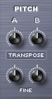
The PITCH area has three sets of controls for
changing the pitch of both Layers; TRANSPOSE, COARSE & FINE. The COARSE and TRANSPOSE controls are
shared by the same knob. Selecting
the label switch below the PITCH knobs will toggle between COARSE and
TRANSPOSE.
TRANSPOSE

The Transpose controls work like MIDI transposition
and pitch changes are made in semitones. Changes in pitch don’t affect the sound quality of the Oscillator. Transpose is most often used to set the
oscillators at different semitone values, such as octaves or different
intervals. Transpose offers the best available sound quality but it is not
Modulatable.
Range -24 semitones to +24 semitones
COARSE

Coarse operates in a similar way to a fine pitch
control, but with a much larger range. Unlike Transpose, using Coarse tuning does affect the sound quality of
the Oscillator, but it is a Modulatable control. COARSE is very useful for wide-range pitch modulation FX.
Range -4800 cents to +4800 cents
NOTE: Changing from Coarse to
Transpose (or vise versa) will not reset the pitch values because they are
separate parameters.
FINE

The fine pitch controls are the most precise,
changing the pitch in 1-cent increments. The Fine controls can shift the pitch 100 cents up or down, or one
semitone each way.
The most common use of fine pitch controls is to
'de-tune' one oscillator a small amount (less that 15 cents) that makes the
oscillators sound richer because of the chorusing effect it provides.
Range -100 cents to +100 cents
EDIT PAGE - Velocity Curves
EDIT PAGE - Velocity Curves
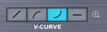
The “V” stands for Velocity. Omnisphere has four velocity curve
presets available on the CONTROLS screen. The first curve is linear, then two exponential curves and the last is
flat. These curves are
provided to quickly adjust the dynamic response of the current Patch to your MIDI
controller and playing style.
LINEAR

The linear curve is the most commonly used
velocity setting. Playing harder
on the keyboard will have a direct effect on any parameter that is modulated
with velocity in an even and linear way.
EXPONENTIAL
POSITIVE

The Exponential Positive curve means that when
playing softly not much effect will be heard, but when playing at a moderate
intensity on the keyboard the velocity modulation will be more dramatic than
with a linear curve.
EXPONENTIAL
NEGATIVE

Exponential Negative has the opposite effect of
Exponential positive – meaning that it’s better suited for more intense
touch and provides the widest musical dynamic range.
FLAT

Omnisphere will receive the same velocity value
with this flat curve. Useful if a
totally consistent and predictable result is desired.
V-CURVE ZOOM

The V-Curve Zoom button provides access to the Velocity Curve Zoom, for precise editing of the Patch’s Velocity
response.
EDIT PAGE - Velocity Curve Zoom
EDIT PAGE - Velocity Curve Zoom
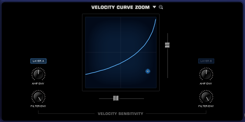
By selecting the Zoom icon next to the different Velocity
curves presets opens the VELOCITY CURVE ZOOM. This page provides detailed controls to create and modify
velocity curves. The Velocity curve
settings are global to the Patch – meaning that curve settings will apply
to both layers, but the amount applied by layer can be controlled by the Layer
A and Layer B.
You can save, copy and load preset Velocity curves from the
drop-down menu next to the VELOCITY CURVE ZOOM header.
CURVE DISPLAY
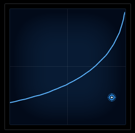
When changes are applied to the SLOPE & OFFSET sliders
(described below) the shape of the curve change will change accordingly in this
display.
AMP ENV (Layer A & Layer B)

The AMP ENV (Amplitude Envelope) independently controls how
much the Amplitude Envelope is affected to the Velocity curve. If the knobs are set to a low level, then
keyboard velocity will have only a small effect on the Amplitude Envelope’s
control of the level of the layer.
FILTER ENV (Layer A & Layer B)

The FILTER ENV (Filter Envelope) independently controls how
much the Filter Envelope is affected to the Velocity curve. If the controls are set to a low level,
then keyboard velocity won’t have much effect on the Filter Envelope’s control
of the Filter.
SLOPE

This horizontal control adjusts the steepness, or slope, of
the velocity curve. If the slider
is set all the way to maximum, the curve will be very steep. Minimum settings will have a horizontal
(or flat) curve.
OFFSET

This vertical slider offsets the velocity curve by raising
and lowering it within the display. At high settings the curve will start at a higher level and moving the
slider down will set the velocity curve to a minimum level.
CONTROL POINT

The Control-Point determines the shape of the velocity curve, whether it’s a positive or negative curve (or even a straight linear curve). The Control Point, OFFSET and SLOPE sliders can create a wide variety of curves. Move the Control Point around the grid by selecting and dragging it until the desired curve is set.
EDIT PAGE - Solo & Glide
EDIT PAGE - Solo & Glide
SOLO

Solo allows the Patch to play monophonically. SOLO mode is most effective when
playing lead or bass lines. It
works in conjunction with the LEGATO button below it, which determines how the
sound is triggered.
LEGATO

Legato is a triggering mode that allows the
envelope and Soundsource to run through their settings instead of re-triggering
with every new note that is played. If LEGATO is not selected, then each new note played will retrigger both
the envelopes and the Soundsource.
NOTE: In vintage synths, Legato
‘ON’ would be referred to as “Single Trigger” while Legato ‘OFF’ would be
“Multi Trigger”
GLIDE

Glide is a portamento effect, which adds a pitch
slide from one note to the next. Omnisphere’s Glide function is polyphonic, which means that every note
that’s played will have a sliding pitch. Selecting the SOLO button above it enables monophonic Glide.
The control slider next to the GLIDE button
determines how slowly or quickly that the pitches slide from one note to the
next. The higher the control
slider is set, the slower the pitch glide between notes.
Range 0 to 2 seconds
GLIDE LEGATO
Glide Legato will change the criteria for when
GLIDE is enabled. If legato notes
are played, then GLIDE will be activated. If quick, staccato notes are played, the Glide effect will not be heard.
GLIDE A B (LAYER BUTTONS)

GLIDE can be used on just one Layer if
desired. By default, when GLIDE is
selected, both A & B will active. If neither A or B is selected, no GLIDE effect will be heard, and the
GLIDE button will turn itself off.
Gliding on one Layer only can be an interesting
musical effect.
EDIT PAGE - Voice, Octave & Gain
EDIT PAGE - Voice, Octave & Gain
VOICES

The VOICES parameter determines the number of
simultaneous notes (also called polyphony) that are playable in a single
Part. Omnisphere is capable of up
to 64 voices of polyphony per part, and the VOICES selector determines the
maximum number of voices that the Part will have.
The higher the number of voices that the Patch
has, the more CPU power it will use, so this is a very important parameter in
Omnisphere. The best approach is
to only set it to the maximum number of notes that are needed for the given
musical application.
The factory Patches have all been set
conservatively, so if more polyphony is needed, increase the number of voices.
NOTE: Voices applies to all
sounding notes, not just the ones that are currently being played. This is important to consider when
playing sounds with longer release times
Range 1-64
OCTAVE

This function raises or lowers the overall pitch
by transposing the patch in 12-semitone increments. There is a total range of five Octaves.
Range -2 to +2
GAIN

The output level of the part can be controlled in
1db increments. The default is
-6db.
Range +10db to -24db
EDIT PAGE - Modulation
EDIT PAGE - Modulation
Modulation adds motion and complexity to sounds. Simply put, modulation is any source that affects a target parameter in some way. The most common form of modulation in synthesizers is vibrato, where an LFO modulates the pitch of an Oscillator. Modulation is used in synths for adding richness and variety to a sound in real-time. Omnisphere’s modulation capabilities are extensive, but simple to use with the Flex-Mod™ system we’ve designed. Omnisphere also features a traditional Modulation Matrix Zoom view that provides more precise control over modulation routings and an overview of all assigned routings.
There are three ways to set up
modulation routings in Omnisphere:
1. Modulations can be set up on the fly by
right-clicking parameters and choosing a modulation source from a drop
down menu.
2. Modulation routings can be defined in the
Modulation section of the EDIT overview.
3. Modulation routings can be configured on the
Mod Matrix Zoom view.
With the wide variety of sources and
destinations, there are literally thousands of potential modulation routings
that can be configured.
EDIT PAGE - Flex Mod™
EDIT PAGE - Flex Mod™
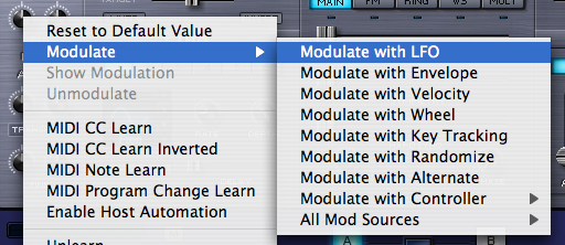
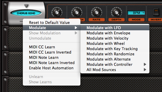
The quickest way to set up a
modulation routing is by right clicking on the control to be modulated*. From the menu, select from the list of
available sources.
The first group of modulation
options in the list is commonly used sources. If there’s more than once source available of a given
type, the next available source will be used automatically. This approach saves a lot of time that
used to be wasted trying to find an unused source.
For example, when “Modulate with
LFO” is selected, the next available LFO will automatically be routed to the
target parameter. This means
if LFO1 is already being used as a modulation source, the Flex-Mod system will
automatically assign LFO2. Of
course any of these automatic routings can be overridden as well.
A complete list of all of the
Modulation sources is provided at the bottom of the menu as “All Mod Sources”,
so specific sources can be chosen if that’s preferred.
After the target parameter’s
modulation source has been selected, the routing is then displayed in the
MODULATION section of the EDIT page.
* Not all
controls are Modulatable, but the majority are.
NOTE: If all six LFOs have been
routed as modulation sources, and “Modulate with LFO” is selected it will
default to LFO1. This is the same
with the modulation envelopes – after four are in use all additional
“Modulate with Envelope” routings will default to MOD Envelope 1.
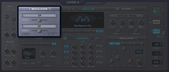
EDIT PAGE - Modulation Section
EDIT PAGE - Modulation Section
The Modulation section has two
functions; to display any existing modulation routings and also to create new
routings. Existing routings can
also be edited here. The key
concept of the Modulation section of the EDIT page is that only one modulation
routing is displayed at a time (the Mod Matrix Zoom shows many routings
simultaneously)
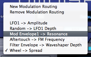
Selecting the drop down arrow on the MODULATION
header will bring up a menu that allows new modulation routings to be created
as well as the removal of existing routings. All of the modulation routings set up in the currently
selected Layer are visible from this list. Selecting any of these routings will allow them to be
displayed and modified in the Modulation section of the EDIT page.
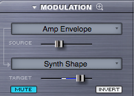
Source Depth

This slider controls the amount of modulation that will be sent from the source to the modulation target. If the slider is set to minimum, the modulation source will have no effect on the modulation target. The higher the setting, the more the source will be affecting to the target. This is useful in controlling the subtlety of the modulation. However it is possible to send too much signal from the source, which causes unusual behavior in the target because the values are out of range.
Target Parameter

This slider is a duplicate of the target parameter – meaning it’s another representation of the parameter that’s being modulated.
Inside the parameter ‘slot’ is a dual indicator. The blue line represents the range of the modulation and the white point indicates the current value of the modulation.
Mute

The currently displayed modulation routing can be muted with this switch. This is a quick way to hear the Patch with and without the modulation routing.
Invert

The Invert button changes the modulation source by reversing the values so it will have the opposite effect on the modulation target.
For example, if the modulation source is an LFO with an ascending ramp wave as its waveform, it will invert the signal to that of a descending ramp waveform.
EDIT PAGE - Modulation Sources List
EDIT PAGE - Mod Sources List

The SOURCES menu brings up a list of the 28
possible modulation sources available in Omnisphere.
These are the 28 available modulation sources in
Omnisphere;
LFO1 – Low Frequency Oscillator 1
LFO2 – Low Frequency Oscillator 2
LFO3 – Low Frequency Oscillator 3
LFO4 –
Low Frequency Oscillator 4
LFO5 – Low Frequency Oscillator 5
LFO6 – Low Frequency Oscillator 6
Alternate – Every keystroke alternates between positive and negative
values (polyphonic)
Random – Every keystroke will generate a random value (polyphonic)
Velocity – MIDI velocity values (polyphonic)
Key Tracking – Values based on what not is played on the MIDI keyboard
Filter Envelope – The output of the Filter Envelope
(polyphonic)
Amp Envelope – The output of the Amp Envelope (polyphonic)
Mod Envelope 1 – The output of Modulation Envelope 1
Mod Envelope 2 – The output of Modulation Envelope 2
Mod Envelope 3 – The output of Modulation Envelope 3
Mod Envelope 4 – The output of Modulation Envelope 4
Orb – The output of the Orb.
Wheel – The value from Modulation wheel MIDI controller (MIDI CC#1)
Aftertouch – The MIDI note pressure value (Channel or Polyphonic Aftertouch)
Pitch Bender - The value from the
Pitch Bend MIDI controller
Breath Controller – The value of a breath controller MIDI
device (MIDI CC#2)
Foot Controller – The value of a MIDI Foot Controller
(MIDI CC#4)
Expression – The value of a continuous MIDI expression (MIDI CC#11)
Sustain – The value from a MIDI Sustain pedal (MIDI CC#64)
Sostenuto – The value from a MIDI Sostenuto pedal (MIDI CC#66)
Soft Pedal - The value from a MIDI Soft Pedal (MIDI CC#67)
Legato – The value from a MIDI Legato Pedal (MIDI CC#68)
User CC – A user-defined Continuous Controller (or MIDI CC value
defined from the System page)
Morphing Source – a special-purpose modulation source
described in the Morphing Modulation chapter
EDIT PAGE - Modulation Target List
EDIT PAGE - Mod Target List

A “Modulation Target” is a parameter that can be
controlled by a source. “Target”
is another word for “Destination”. Omnisphere has an extensive set of over sixty different modulation
targets available. They are
grouped in six categories;
Oscillator
Pitch Coarse – The coarse tuning of the oscillator’s pitch (polyphonic)
Pitch Fine – The fine-tuning of the oscillator’s pitch (polyphonic)
Unison Detune – The amount of detuning of Oscillator
unison voices (monophonic)
Unison Depth - The amount of Oscillator Unison voices added (monophonic)
FM Frequency – The frequency of the dedicate FM modulator (polyphonic)
FM Depth – The depth of the FM modulator (polyphonic)
Ring Mod Frequency – The frequency of the Ring modulator
(polyphonic)
Ring Mod Depth – The amount of Ring Modulation (polyphonic)
Waveshaper Depth – The amount of Oscillator Waveshaping
(polyphonic)
Waveshaper Mix – The blend of the waveshaping signal
(polyphonic)
Waveshaper Bit Crush – The amount of Bit Crushing (polyphonic)
Waveshaper Bit Crush Force – The amount of Bit Crush Force (polyphonic)
Waveshaper Sample Rate – The amount of Sample Rate Reduction (polyphonic)
Waveshaper Sample Rate Animation – The amount of Sample Rate Animation (polyphonic)
Harmonia Mix – The blend of the Harmonia voices with the primary Oscillator (polyphonic)
Harmonia Level 1 – The level of the first Harmonia oscillator (monophonic)
Harmonia Level 2 – The level of the second Harmonia oscillator (monophonic)
Harmonia Level 3 – The level of the third Harmonia oscillator (monophonic)
Harmonia Level 4 – The level of the fourth Harmonia oscillator (monophonic)
Harmonia Detune 1 – The detune amount of the first Harmonia oscillator (monophonic)
Harmonia Detune 2 – The detune amount of the second Harmonia oscillator (monophonic)
Harmonia Detune 3 – The detune amount of the third Harmonia oscillator (monophonic)
Harmonia Detune 4 – The detune amount of the fourth Harmonia oscillator (monophonic)
Sample Timbre – The Sample Timbre parameter in the
Oscillator (polyphonic)
Sample Start – The Sample Start parameter in the Oscillator (polyphonic)
Sample Granular Intensity – The size/intensity of the sample grains
(monophonic)
Sample Pitch Grains – The probability of Granular pitch grains
(monophonic)
Sample Granular Speed/Position – The Speed/Position of the grains (monophonic)
Synth Shape – The Synth Oscillator’s shape (polyphonic)
Synth Hard Sync – The Synth Oscillator’s Hard Sync
(polyphonic)
Synth Symmetry – The Synth Oscillator’s Symmetry
(polyphonic)
Synth Phase – The Synth Oscillator’s Phase control (polyphonic)
Synth Analog – The Synth Oscillator’s Analog control (polyphonic)
Filter
Cutoff – The Filter’s cutoff frequency (polyphonic)
Resonance – The Filter’s Resonance amount (polyphonic)
Filter Mix – The mix between Filter1 and Filter2 (monophonic)
Spread – The Filter’s Spread control value (monophonic)
Filter 1 Cutoff Offset – The Filter 1 cutoff offset value
(monophonic)
Filter 2 Cutoff Offset – The Filter 2 cutoff offset value
(monophonic)
Filter 1 Res Offset - The Filter 1 Resonance offset (monophonic)
Filter 2 Res Offset - The Filter 2 Resonance offset (monophonic)
Filter 1 Spread – The Filter 1 spread (monophonic)
Filter 2 Spread – The Filter 2 spread (monophonic)
Amp
Amplitude* – The amplitude level (polyphonic)
Pan – The stereo panning control (polyphonic)
LFO
LFO1 Rate – The speed of LFO1 (monophonic)
LFO1 Depth – The amount of LFO1 (monophonic)
LFO2 Rate – The speed of LFO2 (monophonic)
LFO2 Depth – The amount of LFO2 (monophonic)
LFO3 Rate – The speed of LFO3 (monophonic)
LFO3 Depth – The amount of LFO3 (monophonic)
LFO4 Rate – The speed of LFO4 (monophonic)
LFO4 Depth – The amount of LFO4 (monophonic)
LFO5 Rate – The speed of LFO5 (monophonic)
LFO5 Depth – The amount of LFO5 (monophonic)
LFO6 Rate – The speed of LFO6 (monophonic)
LFO6 Depth – The amount of LFO6 (monophonic)
Envelope
Amp Env Attack Trim* – The relative AMP Attack
time (polyphonic)
Amp Env Decay Trim* – The relative AMP Decay
time (polyphonic)
Amp Env Release Trim* – The relative AMP Release
time (polyphonic)
Amp Env Speed – The speed of the Amplitude
Envelope
Filter Env Attack Trim* – The relative Filter Attack
time (polyphonic)
Filter Env Decay Trim* – The relative Filter Decay
time (polyphonic)
Filter Env Release Trim* – The relative Filter
Release time (polyphonic)
Filter Env Depth – The amount of the Filter Envelope
Filter Env Speed – The speed of the Filter Envelope
(monophonic)
Mod Env1 Depth – The amount of Mod Envelope1 (monophonic)
Mod Env1 Speed – The speed of Mod Envelope1 (monophonic)
Mod Env2 Depth – The amount of Mod Envelope2 (monophonic)
Mod Env2 Speed – The speed of Mod Envelope2 (monophonic)
Mod Env3 Depth – The amount of Mod Envelope3 (monophonic)
Mod Env3 Speed – The speed of Mod Envelope3 (monophonic)
Mod Env4 Depth – The amount of Mod Envelope4 (monophonic)
Mod Env4 Speed – The speed of Mod Envelope4 (monophonic)
Morphing Modulation
Morphing
Input A – Explained in the Morphing Modulation section
Morphing
Input B – Explained in the Morphing Modulation section
Morphing Input A/B Xfade – Explained in the
Morphing Modulation section (monophonic)
* These parameters appear
exclusively within the Modulation Matrix and are not seen on the GUI.
EDIT PAGE - Effects Modulation
EDIT PAGE - Effects Modulation
The fact that Omnisphere can modulate nearly fifty synthesis parameters is only part of the story. Any of Omnisphere’s modulation sources can be applied to the myriad of FX parameters as well. Just about every single parameter in all of Omnisphere’s 33 effects modules can be modulated, which means there are over 200 effects parameters available on top of all of the synthesis parameters. In total, Omnisphere has nearly 300 available modulation targets!
Effects Modulation can be set up quickly using the same flex-mod system available on the MAIN and EDIT pages.
Modulation Effects Menu
Any effect that’s added to a Layer Effect rack (A or B) is available as a modulation target. After any Effect has been added to a Layer rack, a new category called “Layer Effects” will appear at the bottom of the list of target categories.
NOTE: Only FX assigned to a Layer Rack are available as Modulation Targets - FX in the COMMON rack are not.
When any modulatable parameter is right-clicked, the same list of Modulation options appears when a synthesis parameter is right-clicked. All of the Modulation options are the same.
After a parameter has been assigned as a Modulation Target, the control will become shaded with a bluish tint (in the example below, the Delay control is now blue).

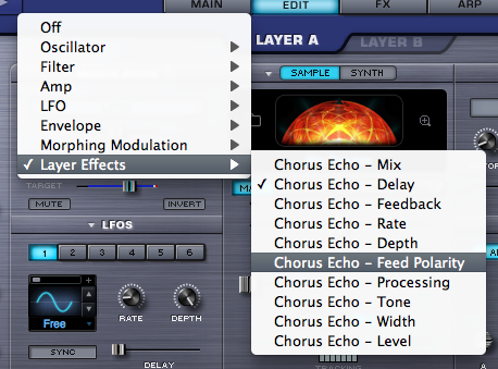
These parameters will be available as long as the effect module is assigned to the Patch – meaning they will no longer appear if they effect is removed from that Layer’s rack.
EDIT PAGE - Mod Matrix Zoom
EDIT PAGE - Mod Matrix Zoom
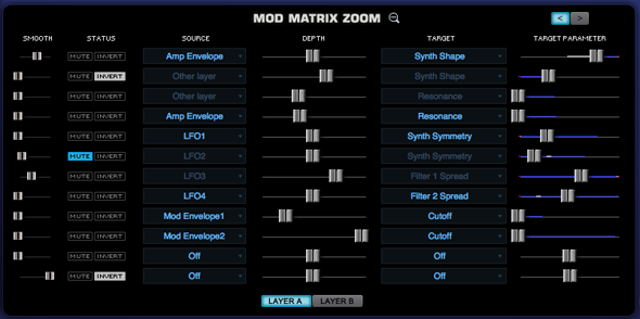
Selecting the Zoom icon on the Modulation header
will open the Mod Matrix Zoom view. The Mod Matrix view offers precise control over all of the modulation
routings in the Patch. The
advantage of this zoom view is that the many routings can be displayed for
editing simultaneously.
There are the same Source/Target sections, Depth
and Target Parameter controls from the EDIT overview page, as well as some
controls unique to the Mod Matrix Zoom, like smoothing. There are two sub-pages in Mod Matrix
Zoom, each with twelve modulation routings making for a total of 24 possible
modulation routings available per Patch.
It’s important to note that Omnisphere also has a
number of fixed modulation routings as well. Many of the typical routings have already been hardwired in
the STEAM engine, so they don’t have to be assigned. These include Velocity control over Envelope depth, Key
Tracking of Filter depth, Filter Envelope to Cutoff, and so on.
Page Switch

Toggles between the two Mod Matrix sub-pages. It’s generally a good rule of thumb to
fill up the first modulation page before any mod routings are added on the
second modulation page. Each page
displays twelve routings at a time. The Mod Matrix shows modulation routings for both Layers simultaneously.
Smoothing

The modulation Smoothing control takes the incoming
modulation source and slows the sharper points down, smoothing them out. This means that the character of the
modulation source will not have quite as drastic or harsh an effect on the
modulation destination. It works
in a similar way to the Lag processors on some vintage synthesizers. This is the same principle that is used
in Glide/Portamento, but applied to any source and target.
Status

This is a shared area with two switches, Mute & Invert.
The Mute control virtually disconnects the modulation
routing. This is a quick way to
hear what kind of effect it’s having on the part.
The Invert control allows toggles between positive or
negative modulation.
Source

The source area displays and selects the modulation source
to control a target. Selecting the source will open up a menu of 28 modulation
sources and “Off” – which negates any modulation source.
Depth

This control determines to what degree the source affects
the modulation target. The higher
the setting, the more the Source will affect the target. Depending on the kind of Modulation
Source used, it is possible to send too much signal from the Modulation Source,
which causes unexpected results in the target. This is explained in the section below on the Target
Parameter.
Target

The Target is the destination for the Source’s modulation
output. Omnisphere has a large
number of modulation targets, including synthesis parameters as well as effects
parameters.
The full list of Targets is listed in the MODULATION section here
Target Parameter

This control represents the setting of the target parameter
– meaning it’s another representation of it.
Inside the parameter ‘slot’ is a dual indicator. The blue line represents the range of
the modulation and the white point indicates the current value of the modulation.
Layer Display Switches

These buttons allow viewing the active modulation routings
on either layer. When Layer A
or Layer B is selected, that layer’s modulation routings are shown in bright
blue text, while the other layer’s routings are disabled.

MOD MATRIX ZOOM – Morphing Modulation
MOD MATRIX ZOOM –
Morphing Modulation
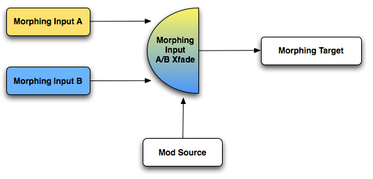
Omnisphere has a very special modulation feature that goes
beyond the standard method of modulating a single target with a single source,
called morphing modulation. This
system uses dual-sources to modulate a single target and adds a morphing
component to interactively crossfade between the outputs of the two modulation
sources. This can create very
dynamic modulation routings and effects.
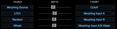
There are four components to Morphing Modulation, which
means setting up a Morphing Modulation routing will use four slots in the
Modulation Matrix.
First a target must be designated; this is the parameter
that will be modified by the morphing modulation. Two different modulation sources need to be defined. The degree that the two modulation
sources will be blended together is determined by the Morphing Input A/B Xfade
source. This modulation source
will control how the two morphing inputs are combined before they are sent to
the target.
Morphing Source

This defines that target of morphing modulation. It can be any of Omnisphere’s
modulation targets. Once “Morphing
Source” is selected and a Target parameter is designated, then the two morphing
modulation inputs must be defined.
Morphing Input A

This is one of the two sources that will become a Morphing
Input. The sum of both Morphing
Input A and B will be sent to the target defined in Morphing Source routing, so
its necessary to define Morphing Input A as the target.
Morphing Input B

This is the other morphing source that will modulate the
target. After the Source is
chosen, then Morphing Input B needs to be selected as the target.
It’s important to make the Source in Morphing Input B
different from Morphing Input A – if they are the same source then the
morphing will have no effect.
Morphing Input A/B Xfade

This routing is what defines what will control the morphing
between the two A/B inputs – so the Source here should be one that is
suited to this kind of cross fading.
Suggested Morphing Inputs for A/B Xfade;
Wheel
Velocity
LFOS
Envelopes
EDIT PAGE - Oscillator
EDIT PAGE - Oscillator
The Oscillator is the heart of Omnisphere’s vast
synthesis capabilities. It
has a ‘split-personality’ since each Layer’s Oscillator can have either
high-definition, streaming sample-playback or dynamic, real-time, DSP-generated
waveforms. The Oscillator’s
extensive synthesis capabilities vary depending if Sample mode or Synth mode is
utilized.
SAMPLE MODE
Omnisphere’s massive core-library is comprised of
over 40GB of high-definition, sample-based sounds, called Soundsources, to use
as a source for synthesis. These
Soundsources cover a wide spectrum of sounds, from simple raw waveforms to
psychoacoustic samples, to morphing textures, warm voices, choirs, vintage
keyboards, analog synths and a best-of selection from our award-winning sample
libraries.
SYNTH MODE
These are DSP waveforms, generated in real-time
by the STEAM engine, that are similar in principle to vintage synthesizer
waveshapes. They have the same
rich character of classic synthesizers, but with a much greater level of
control and sound shaping abilities. The Synth Oscillators are not modeled to emulate any particular brand of
synthesizer, but instead were extensively tweaked to have a great-sound and
versatile character that’s unique to Omnisphere.
The combination of both types of sound generation
makes Omnisphere a true hybrid instrument, able to transform both the SAMPLE
and SYNTH sounds via a wide range of complex synthesis methods.
The STEAM engine goes beyond traditional
synthesizers by including a set of dedicated oscillators for Hard-Sync,
Frequency Modulation, Ring Modulation and the unique Voice Multiplier. In fact,
a single part can have up to 24 oscillators used per voice!
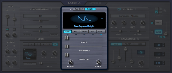
SAMPLE/SYNTH MODE SELECTOR

Selecting either mode switch will determine
whether the Layer will be able to load a Soundsource (SAMPLE) or will utilize a
DSP Waveform (SYNTH).
SAMPLE MODE does not load a Soundsource by
default. First a Soundsource must
be selected from the Soundsource Browser.
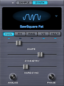
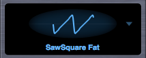
SYNTH MODE defaults to the “SawSquare Fat”
waveform.
OSCILLATOR SUB-PAGES

Each of the five sub-pages contain a wide set of
synthesis functions that can applied to the Oscillator. The default sub-page is
MAIN.
MAIN |
The Oscillator modifiers |
FM |
Frequency Modulation synthesis |
RING |
Ring Modulation synthesis |
WS |
The Wave Shaper |
MULT |
The Voice Multiplier |
INDICATOR SWITCHES

The Indicator Switches below the sub-pages indicate
activity in that area. They also
double as mini-power-switches for those functions, so that quick comparisons
can be made. It’s also useful to
see at a glance which features are currently in use. Selecting the Oscillator
sub-page buttons will not enable their functions, but selecting the small
indicator switches below the sub-pages will.
NOTE:
The MAIN sub-page’s indicator is unique because it doesn’t function as a switch
and will remain unlit until the default settings are changed.
EDIT PAGE - Sample Mode
EDIT PAGE - Oscillator Sample Mode

When in SAMPLE mode, the OSCILLATOR plays back Soundsources from Omnisphere’s massive core-library. Soundsources range from complex, multi-sampled sounds to single sample mapped across a keyboard.
SAMPLE MAIN
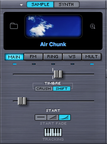
Soundsource Display
The Soundsource Display area contains an image of the loaded Soundsource, and provides controls to access to the Soundsource Browser and Soundsource Zoom View
Image
Whenever you load a Soundsource into the Layer, it will include an image representing the Soundsource. This makes it convenient to see at a glance the type of Soundsource that is loaded.
Browser Access
Selecting the Folder icon, the Soundsource Name Display, or the Soundsource Image will open the Soundsource Browser.
EDIT PAGE - Oscillator Timbre Control
EDIT PAGE - Oscillator Timbre Control

The TIMBRE slider varies the harmonic tone
quality of the Soundsource by altering the tonal characteristics of the
original sample(s) in different ways. There are two TIMBRE modes, CRUSH and SHIFT. The center-point of this bidirectional slider is the null
point – meaning no TIMBRE change will occur.
TIMBRE CRUSH MODE – Polyphonic Bit-Crushing
(Distortion) and filtering are applied to the Soundsource. Bit-Crushing with a Low-Pass Filter is
applied left of the center-point. Right of the center-point, Bit-Crushing with a High-Pass filter is
applied. Timbre Crushing works
effectively with any Soundsource.
TIMBRE SHIFT MODE - Transposes the mapping of the
samples in one direction and changes the pitch in the opposite. This results in significant harmonic
changes in the Soundsource. Moving
the TIMBRE slider to the right will transpose the sample mapping down and the
pitches up and vise versa when moving it to the left.
When SHIFT is applied, in either direction, the
character of the Soundsource can change significantly. And when the SHIFT is used as a
modulation target, the character of the Soundsource can change dynamically.
NOTE: The more samples the
Soundsource has mapped across the keyboard, the more effective that TIMBRE
SHIFT will be. Conversely, with a
texture or other Soundsource that only contains a single sample, SHIFT will
have no effect.
TIP: To see how many samples the
Soundsource uses, select the Soundsource Zoom icon at the top of the OSCILLATOR
header and refer to the ‘SPECS’.
NOTE: Because of the way TIMBRE
SHIFT works, changes to the modulation of the TIMBRE slider must be retriggered
to hear the effect. TIMBRE changes
can’t be heard on a sustained note.
EDIT PAGE – Oscillator Sample Start
EDIT PAGE – Oscillator Sample Start
The START control determines at what point in the
sample that it begins when the oscillator is triggered. This setting will vary
depending on the number of samples in the Soundsource.
This feature has several applications. First, it can remove sharp attacks or
clicks at the start of a sample.

Soundsources can have a single sample mapped
across the entire keyboard (Textures are a typical example of this). Other types of Soundsources often have
many samples mapped to different ranges on the keyboard. These ranges are called ‘zones’
The number of zones determines the maximum range
of the Start slider. If the
Soundsource has more than 12 zones mapped, the range of the START slider is 1
second. If it has less than 12
zones, then the START slider’s range can be up to 90 seconds. The .60 range is especially useful when
modulating long evolving Texture Soundsources and using the Arpeggiator.
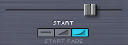
SAMPLE START FADE

These are mode switches that control the shape of
the sample start point. This can
be useful for eliminating clicks that might happen at certain sample start
offsets. These three mode switches
set the duration of fade-in;
 |
No Fade-in |
| |
|
 |
Medium Fade-In |
| |
|
 |
Maximum Fade-In |
EDIT PAGE – Sample Oscillator Tracking
EDIT PAGE - Sample Oscillator Key Tracking

If the TRACKING (also known as Keyboard Tracking)
switch is enabled then the pitch of the Soundsource will track the keyboard,
meaning the root pitch of the samples will be changed with each key.
When TRACKING is disabled, the Oscillator will
not track the keyboard and depending what kind of Soundsource is loaded, some
keys may have static pitches.
Single Sample |
All of the keys will play the same pitch |
| |
|
Multi-Sample |
The range of each sample will have the same
pitch. For example, if there is
a different sample mapped to each octave, then each octave will only play a
single pitch. |
| |
|
Chromatic Sample |
Since every key has a sample, there is no
apparent change when Keyboard Tracking is disabled. |
Disabling Keyboard
Tracking can be useful for drones, unusual sound effect or strange tonal
combinations.
EDIT PAGE - Soundsource Zoom
EDIT PAGE - Soundsource Zoom
The Soundsource Zoom Edit View provides controls that let you manage several aspects of the complex Soundsources in Omnisphere. It is particularly useful when loading Trilian Soundsources into Omnisphere using Omnisphere Library Integration.
Using the Soundsource Edit Zoom you can mix the levels of multiple channels, such as Microphone and Direct Pickup outputs, select the desired Release Noise and adjust its level, enable the special Legato articulation triggering, and other adjustments. Deceptively simple, this single interface provides important sound shaping and memory management capabilities.
NOTE: Some of the controls are intended for use with Trilian sounds loaded into Omnisphere. For example, Omnisphere sounds don’t currently include Legato Soundsources, so these controls will have no effect on Omnisphere Soundsources.
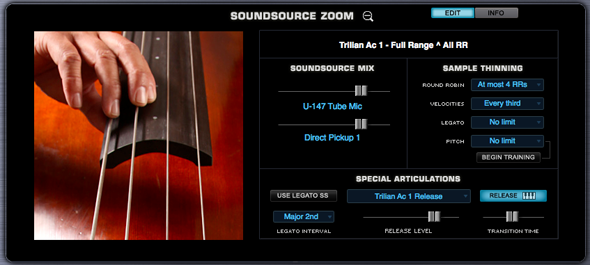
Selecting the Zoom icon in the Soundsource Display will open the Soundsource Zoom Edit View by default. The Soundsource Zoom has two sub-panes, the Edit View and the Info View, accessed by selecting the EDIT and INFO buttons.
The Soundsource Zoom Info View provides the most information about the loaded Soundsource, with details about the origin of the samples and suggestions for their application. It also displays a large representative image of the loaded sound. The Soundsource Zoom Info View is covered in detail in the Browser section of the guide.
The Edit View is divided into two main areas, the Image area and the Controls area. The Image area contains a large, representative image of the loaded Soundsource. The Controls area consists of a Soundsource Name Display, Soundsource Mix section, Special Articulations section, and the Sample Thinning section.
EDIT PAGE - Soundsource Zoom Mix
EDIT PAGE - Soundsource Zoom - Mix
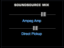
When using Omnisphere Library integration it is possible to load Trilian Soundsources in Omnisphere. Most Trilian Soundsources are multi-channel, and these controls allow you to mix the output channels. In some cases, the two channels are used for double tracking instruments (such as in Trilogy’s Fretless section).
The Soundsource Mix section provides level faders for both channels. Mixing the two sources can have a strong affect on the sonic characteristics of the instrument and how it sits in your mix.
Moving the faders to the left lowers the level, moving them to the right increases the level.
If you only want to hear one of the channels, simply move the level for the other channel all the way to the left.
EDIT PAGE - Soundsource Zoom - Special Articulations
EDIT PAGE - Soundsource Zoom - Special Articulations
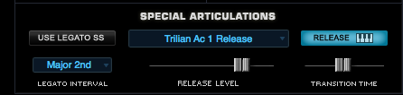
Special Articulations are additional Soundsources loaded in the background that will be automatically triggered depending on how a passage is performed. The Special Articulations are Legato Soundsources (samples of actual Legato performances), and Release Noise articulations.
Omnisphere Soundsources don’t use Special Articulations, but most Trilian Soundsources do. When using Omnisphere Library Integration, the Special Articulations section lets you control how these articulations are applied to the primary Soundsource.
NOTE: It is possible to apply Trilian Release Noises to Omnisphere Soundsources by selecting from the available Release Noises in the drop down menu.
Use Legato SS

When Legato Soundsources are available and loaded, enabling the Use Legato SS button will automatically trigger these Special Articulation samples when playing legato-phrased notes within the specified Legato Interval, providing added realism and nuance to the instrument sound.
NOTE: Omnisphere sounds don’t currently include Legato Soundsources, so this control will have no effect on Omnisphere Soundsources. It is most useful when loading Trilian sounds into Omnisphere.
Legato Interval

From this menu it is possible to select the interval within which the Legato Soundsources will be triggered. The possible ranges are from one semitone to two octaves.
Legato Rules
In Trilian Soundsources where Legato Soundsources are available, the Use Legato SS feature enables very realistic hammer-on, pull-off and other types of performance phrasing. It allows for a very natural playing style, and great sounding Legato trills!
Enabling Use Legato SS will change the way the instrument responds to notes that are played Legato. Successive Legato notes that are played within the specified Legato Interval will behave much like a lead synth using SOLO mode. That is, the next note played will cut-off the previously played note. If you sustain the cut off note, it will sound again when you release the successive note. The key difference is that Legato Mode is actually polyphonic.
Notes which are played Legato, but are outside the specified Legato Interval, will not trigger the Use Legato SS behavior.
NOTE: The Use Legato SS button only changes the behavior of the Part. In order to hear the Legato Soundsources, make sure “No Limit” is selected in the Sample Thinning - Legato menu. This will allow the Legato Soundsources to load, and can add a live, dynamic quality to the sound during performance.
NOTE: "Use Legato SS" is a Patch Common parameter. Changing its setting will affect both Layers in the Patch.
Release Soundsource Menu

Release Soundsources are triggered only after a note has been released.
This menu lets you select the Soundsource used for Release Noises. You can also select “No Release Soundsource” if none are desired. Some Soundsources have multiple sets of Release Noises (e.g. a softer set), and you can try mixing the Release Noises from sounds other than the one loaded.
Release Key Tracking

When the Release Key Tracking Button is enabled, the pitch of the Release Noise will track the keyboard. If it is disabled, the Release Noise will only play at the pitch of the root note.
Release Level

This level fader is used to mix the level of the Release Soundsource. Use it together with the Soundsource Mix faders to set the balance you prefer.
When experimenting with mixing Release Noises, try mixing them louder for up-tempo tunes, and lower them for tunes with slower tempos.
If the fader is all the way to the left, no Release Soundsource will be heard. Moved all the way to the right, will make the Release Soundsource very prominent. A setting of around -3dB is usually a good starting point for a natural sound.
NOTE: The Amp Envelope Release Time must be set long enough to hear the decay of the Release Noise Soundsource.
NOTE: Legato and Release Noise Soundsources load after the primary Soundsource samples have finished loading. If you have Release Noise Soundsources enabled, you can start playing before they have loaded, but you will hear long sustains ringing instead of the noises. This is because release times for the amp envelope are set long to let the full Release Noises through.
Transition Timing

This fader affects the transition time between the sustained sample release and the Release Noise Soundsource. It controls how long the note-on samples decay after the note is released, so that the transition between the sustained samples and the release noise samples is musical.
At higher settings you will hear an overlap of the sustained sample release time, and the trigger of the release noise. If the fader is all the way to the left, there will be no overlap.
Amp Release and Release Soundsources
When no release Soundsource is selected, you will hear the same note-on sample you initially triggered when you let go of the key, so the Amp release time has the same musical result that you normally would expect on any synth. For example, all the synth bass patches in Omnisphere and Trilian are programmed with no Release Soundsource, so they behave this way.
If a release Soundsource is selected, then you'll hear that new Soundsource which consists of just the release noises triggered when you let go of the key. Note that the Amp release feature is still working, but is now affecting the amp release of the noise samples only. All the Electric and Acoustic Basses in Trilian are set-up this way and have their Release Times set quite high so that the full decay of the noise samples can be heard.
The Transition time is an additional control which affects how long the note-on samples decay after the note is released, so that the transition between the sustained samples and the release noise samples is musical.
EDIT PAGE - Soundsource Zoom - Thinning
EDIT PAGE - Soundsource Zoom - Thinning
In addition to Special Articulations, Soundsources may also include multiple Round Robin samples and Velocity switched samples.
For this reason, a fully loaded Soundsource can use quite a bit of memory. The Sample Thinning interface helps to manage the use of those resources.
By limiting the number of Round Robin samples, or the Velocity switched samples, or by turning off Legato Soundsources, you can dramatically reduce memory used.
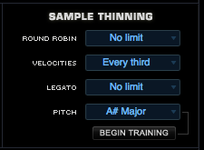
Round Robin
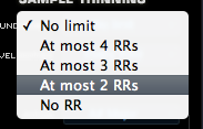
To limit the number of Round Robin samples that are loaded, select an option from the Round Robin menu.
You can choose a setting that ranges from “No RR” too “At Most 4 RR”. Select “No Limit” to allow all Round Robin samples to be loaded.
Velocities
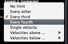
Soundsources can include a very large number of Velocity switched samples, which is great for very realistic and expressive playing. However, if you need to conserve system resources, you can choose to thin the amount of Velocities using this menu.
No Limit
Will load all Velocity switched samples.
Every other
Will load every other Velocity switched sample.
Every third
Will only load every third Velocity switched sample.
Every fourth
Will only load every fourth Velocity switched sample.
Velocities above
Selecting a value from this menu, for example, 64, will only load Velocity switched samples mapped to a Velocity of 64 and above.
Velocities below
Selecting a value from this menu, for example, 100, will only load Velocity switched samples mapped to a Velocity of 100 and below.
NOTE: When thinning Velocities, there are no gaps in the sound. The remaining Velocity switched samples will adjust to be triggered across the full Velocity range.
Legato

This menu has two options, No Limit and None, which determine whether or not Legato Soundsources will be loaded with the sound.
If No Limit is selected, Legato Soundsources will be loaded if the Soundsource has Legato Soundsources associated with it. If None is selected, the Legato Soundsources will be unloaded.
TIP: If you choose to load the Legato Soundsources, you must also enable the Use Legato SS button to trigger them when playing.
NOTE: If you are not using the Use Legato SS feature, it’s a good idea to unload the Legato Soundsources (by selecting None from the menu) to conserve system resources.
NOTE: You can think of the difference between the Legato Thinning menu, and the Use Legato SS button in this way: The Legato menu controls whether the Legato Soundsources will be loaded or not, while the Use Legato SS button determines the behavior of the Part (whether it will “solo” notes played Legato that are half step or a whole step apart).
Pitch Thinning
A Soundsource can contain thousands of samples mapped across the full keyboard range. Pitch Thinning lets you limit the samples that are loaded to match either a “trained” range of played notes, or a selected Scale or Interval. Using Pitch Thinning can substantially reduce the number of samples loaded with the Soundsource.
TIP: Although only a limited set of samples will be loaded, this won’t result in “silent zones” on the keyboard. All notes will still play, but will be stretched from the nearest pitched sample.
Trained Pitch Thinning


With Trained Pitch Thinning, you can load only the samples used during a performance.
For example, if you are working on a simple melodic phrase that has notes in a limited range, say from C2 to C4, by using Trained Pitch Thinning, you can speed up load times, and reduce memory usage by loading only the samples used in that range.
If you have recorded an Omnisphere part in a song, and want to speed up load times and conserve memory, you can apply Trained Pitch Thinning by playing the MIDI clip in the host. Omnisphere will then only load the samples used in the actual phrase.
To use Trained Pitch Thinning, select the Begin Training button. Play a range of notes (or a MIDI clip in the host), and then select the Finish Training button. This will limit the loaded samples to the note pitches that were played during training.
Pitch Thinning Using Scales & Intervals
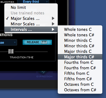
To limit loaded samples to a specific Scale or Interval, select the Pitch Thinning drop-down menu, and select an option from the available sub-menus. You can select from Major or Minor Scales, or from a variety of Intervals.
NOTE: The Pitch Thinning options on the Soundsource Zoom Edit View are the same as those found on the Patch & Multi Browser “Lite Version” Zoom. However, the Browser’s Lite Version feature affects the entire Patch or Multi, while the Soundsource Zoom options affect only the individual Soundsource. Using the Soundsource Zoom thinning options, you can apply different thinning options to each Layer in a Patch.
NOTE: All Thinning options applied here are saved with the Patch or Multi, and are recalled the next time you load them.
EDIT PAGE – Oscillator Synth Mode
EDIT PAGE - Oscillator Synth Mode
The SYNTH waveforms are DSP-generated, and are
similar to classic analog waveforms, but with a greater level of dynamic
control. SYNTH mode features
an oval representation of the waveshape, called the Waveform Display. Changes that are made to the three
unidirectional sliders in the MAIN section below will dynamically and visually
alter the contour of the waveform.
EDIT PAGE – Oscillator Synth Waveforms
EDIT PAGE – Oscillator Synth Waveforms
By selecting anywhere in the Waveform display a
drop-down menu will appear with a list of the five available waveform
types. All five waveforms are
hybrids, meaning they are mixtures of different waveshapes and their contours
can be changed dynamically.
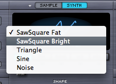
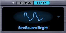
SawSquare Fat Waveform
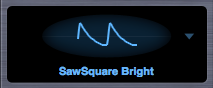
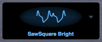
SawSquare Bright Waveform
These two waves can be traditional Sawtooth or
Square waves – and anything in between – which is why they are both
called SawSquare. Moving the SHAPE
slider in the MAIN sub-page will demonstrate the continuous contour change from
a Sawtooth to Square.
The Bright and Fat versions of the SawSquare
waveform are similar, but with a different character. The SawSquare Bright has a bit leaner and buzzier timbre and
is excellent for polyphonic applications. The SawSquare Fat has a thicker
sound, especially in the low end and is ideal for monophonic lead sounds.
Triangle Waveform
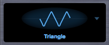
A Triangle wave is more symmetrical than the
SawSquare waveforms and has a mellower character, because of fewer
overtones. By moving the SHAPE
slider towards maximum it will sound richer and more like a Square wave.
Sine Waveform
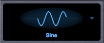
The sine wave is the most symmetrical and since
it has no overtones, it sounds very pure. But with the SHAPE, SYMMETRY and HARD SYNC controls, overtones can be
added to alter its character.
Noise Waveform
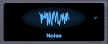
White Noise contains all frequencies, which
therefore is pure noise. Since
changing the wave’s contour with the SHAPE control would not normally make any
difference to noise, the three sliders in the MAIN section have different
functions when the Noise waveform is selected.
EDIT PAGE – Oscillator Synth Shape
EDIT PAGE – Oscillator Synth Shape

This control is unique to the SYNTH waveforms in
Omnisphere. Moving this slider can
modify the contour of any of the five waveshapes. The waveform display will dynamically change the waveshape
as the SHAPE slider is moved.
The SHAPE slider is modulatable which can add
movement and variation to the sound.
NOISE waveform only - SHAPE becomes a complex
filter control, which varies from white noise (all frequencies) at the minimum
setting, to pink noise (reduced high frequencies) at the maximum setting.
EDIT PAGE – Oscillator Synth Symmetry
EDIT PAGE –
Oscillator Synth Symmetry

Symmetry varies the span of the waveform and is most
commonly used for Pulse-Width modulation. This is especially useful when SYMMETRY is used as a modulation
destination, as it adds shifting tone color and movement to the sound. The Symmetry control can vary the span of all waveforms (except
Noise).
NOISE waveform only - The SYMMETRY slider becomes a
morphing filter that sweeps through four different types of filters. Starting at the minimum setting with
low pass to a notch filter, then to a high pass and finally to band pass at
maximum setting.
EDIT PAGE – Oscillator Synth Hard-Sync
EDIT PAGE – Oscillator Synth Hard-Sync

Hard Sync was a feature on some analog
synthesizers, which gave the timbre a "throaty" dipthong type of
sonic characteristic when swept. Hard Sync was popularized on synthesizers like
the Prophet Five and the early Oberheim synthesizers for more metallic and
aggressive timbre, especially useful for lead sounds. Hard Sync is achieved by
using two oscillators, one which is the ‘master’ and the other the ‘slave. The slave is forced to restart its
waveform when hard-synced with the master oscillator and the master controls
the pitch. So any changes in the
slave oscillator’s pitch don’t change the pitch of the master, they change the
overtones and harmonic structure instead.
In the past, an oscillator would need to be
sacrificed to get the hard-sync effect, but Omnisphere has a hidden, dedicated
oscillator just for hard-sync. The
hard-sync oscillator becomes the slave and the Oscillator’s waveform is the
master.
NOISE waveform only - HARD SYNC control acts as a stereo width
control that begins with monaural setting at the minimum setting and gradually
spreads the noise into both right and left channels towards the maximum
setting.
EDIT PAGE – Oscillator Synth Analog Control
EDIT PAGE –
Oscillator Synth Analog

The Analog control allows inconsistency to be introduced
into the pitch and phase of the oscillator, which makes Omnisphere sound and
behave more like a vintage analog instrument. When the Analog control is set to 50% and lower, it
destabilizes the phase of the oscillator. After 50% it will also destabilize the pitch. As the Analog control is increased past 75% the pitch will
become heavily detuned.
NOTE: The Analog control has an affect on Unison voice
too, of if Unison detuning is too drastic, it may be desirable to reduce the
Analog control.
EDIT PAGE – Oscillator Synth Phase Control
EDIT PAGE –
Oscillator Synth Phase

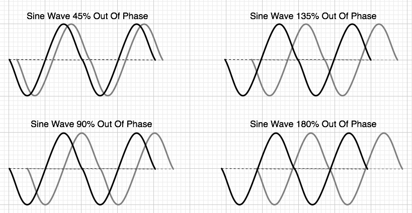
The PHASE control will only have an audible effect when it
is heard combined with another layer, as phase changes can only be perceived
when they are in relation to another audio signal.
The best way to understand the PHASE control is to set up a
SYNTH sound on Layer A (with the ANALOG control to zero). Then, from the UTILITY menu select the
Copy Layer option and select Layer B and select the Paste Layer option from the
UTILITY menu. This way two identical Oscillator Layers will be sounding and
changes in the Phase can easily be heard.
If the PHASE control is at minimum, then the Oscillator will
be triggered at the start of the waveform. As the value is increased, the point in the waveform that
the Oscillator will be triggered will be moved and it will be out of phase with
the other Layer. When the
horizontal slider is set to maximum, it will be 180 degrees out of phase the
other Layer’s Oscillator.
Many interesting composite waveforms can be created with the
Phase control this way, and this technique is particularly useful for Synth
Bass sounds.
NOTE: The PHASE is best utilized when the
ANALOG control, also in the MAIN section, is set to a minimum value.
EDIT PAGE – Oscillator Frequency Modulation
EDIT PAGE –
Oscillator Frequency Modulation
FM stands for Frequency Modulation. FM has been a feature on synthesizers
since the 1960s, but it was most famously realized in Yamaha’s DX/TX series of
digital synthesizers in the 1980s. It was well known for producing glassy, metallic sounds and for creating
sound that are more harmonically complex.
FM is a form of audio synthesis where the timbre of one
waveform, called the “carrier”, is changed by modulating it with the frequency
of another waveform, called the “modulator” – hence Frequency Modulation
synthesis.
FM can take simple waveforms, like sine waves, and make them
sound quite complex. In Omnisphere,
the exciting thing is that any Soundsource or DSP waveform in Omnisphere can be
modulated with FM.
Each Layer in Omnisphere has a dedicated, hidden FM
oscillator, which acts as the modulator; so the other Layer’s Oscillator is not
required for FM synthesis to work. This dedicated Modulation Oscillator can utilize different waveforms and
both its frequency and depth can be shifted and modulated.
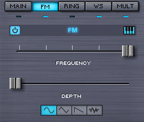
FM POWER SWITCH

Turns the FM modulating oscillator on or off.
FM KEYBOARD TRACKING

The small music-keyboard switch enables or disables Keyboard
Tracking. The Keyboard
Tracking button determines whether the modulator oscillator tracks the
keyboard.
If the Keyboard Tracking is turned on, then the modulator
oscillator will track the keyboard, meaning it will change pitch with the
keyboard. If Keyboard Tracking is
off, the modulation oscillator will not change pitch with the keyboard, it will
stay the same pitch no matter what key is played. This can be useful for more clangorous sounds.
FM FREQUENCY

Controls the frequency of the modulator oscillator. Because the modulator is unheard, it
does not change the pitch of the original Oscillator. Instead it alters the timbral characteristics of the
Oscillator’s waveform.
When this horizontal slider is set to just above the
minimum, it can produce LFO-type pitch effects. Moving the slider towards the maximum increases the
frequency and begins to oscillate fast enough that it will introduce timbre
changes.
The notches along the FREQUENCY slider are markers for the
frequency ratios that will produce the most musically useful results.
These musically useful values at the notches are decimal
versions of these ratios - 1/4, 1/2, 3/4 and 1 – represented as .250,
.500. .750 and 1.00.
Range 0.000 to 1.000
FM DEPTH

Controls the modulator’s depth. The higher the DEPTH slider is set, the more the dedicated
modulator is affecting the timbre of the OSCILLATOR.
Range 0.000 to 1.000
FM WAVEFORM
Many FM synthesizers use only Sine waves, but Omnisphere’s
modulator can use any one of four different waveforms. The four mode switches are for Sine,
Triangle, Sawtooth and Noise. Each
successive waveform has more overtones and so will add a brighter timbre.
In general FM works better when beginning with a simpler,
more pure sound than a sound with a lot of complexity to start with.
EDIT PAGE – Oscillator Ring Modulation
EDIT PAGE – Oscillator Ring Modulation
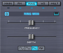
RING is short for Ring Modulation, which is similar in
concept to FM (and the parameters are exactly the same as those in the FM
sub-page). In Ring Modulation the
frequencies of both oscillators are multiplied, which changes their overall
amplitude, so it’s can also be referred to as Amplitude Modulation.
Traditionally Ring Modulation is used as an effect to create
high-frequency, clangorous overtones. However, Omnisphere’s Ring Modulator is polyphonic and can track the
keyboard – meaning the pitch does not have to be fixed; it can follow the
pitch of the keyboard. The result
is something much more musical and useful than a traditional Ring Modulator.
RING MOD
POWER SWITCH

Turns the modulator oscillator On or Off.
RING MOD KEYBOARD TRACKING
The Keyboard Tracking for the Ring Modulator works just like
it does in the FM section. Most
Ring Modulators do not track the keyboard, which is part of the character of
their sound, but Omnisphere provides the option to enable Keyboard Tracking if
required.
If the Keyboard Tracking is turned on, then the Ring
Modulator oscillator will change pitch with the keyboard. If Keyboard Tracking is turned off, the
modulation oscillator will remain the same pitch no matter what key is played.
RING MOD FREQUENCY

Controls the frequency of the modulation oscillator. When the FREQUENCY slider is set to
minimum value, very slow modulation is heard. Sweeping thru the different values will cause different
overtones become more pronounced, because the modulator oscillator is in the
audio range.
The notches along the FREQUENCY slider are markers for the
frequency ratios that will produce the most musically useful results. Just like in the FM section, the most
musically useful values are at the notches. They are represented as .250, .500. .750 and 1.00.
Range 0.000 to 1.000
RING MOD DEPTH

This horizontal slider controls the depth of the Ring
Modulation, meaning how much interaction occurs between the Oscillator and the
modulation oscillator.
Range 0.000 to 1.000
RING MOD WAVEFORM
Ring Modulators typically only use a Sine wave. The dedicated RING oscillator in
Omnisphere can use any one of four waveforms; Sine, Triangle, Sawtooth and
Noise. Each successive waveform
has more overtones and will introduce a brighter, more harmonically rich
character to the OSCILLATOR’s waveform.
EDIT PAGE – Oscillator Wave Shaper
EDIT PAGE –
Oscillator Wave Shaper
Omnisphere’s Wave Shaper takes the Oscillator’s waveform and
passes it thru mathematically generated curves that add various types of
distortion, which changes the waveform’s harmonic content.
Instead of being a stand-alone effect, Omnisphere’s Wave
Shaper is part of the Oscillator, and is polyphonic, making it a synthesis
function and not just an effect. This means that the Oscillator’s can have more harmonic richness without
the clashing sound heard when playing chords thru a monophonic distortion (such
as a fuzz box). Polyphonic
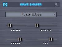
distortion is far more versatile musically. The Wave Shaper section in the Edit Page has a basic set of parameters. The complete set of Wave Shaper controls are available in the Wave Shaper Zoom page.
WAVE SHAPER POWER SWITCH

This turns the Wave Shaper section on or off.
WAVE SHAPER PRESETS
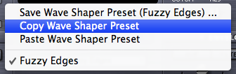
Wave Shaper Presets can be copied, pasted or saved from this menu.
CRUSH

Bit-crushing introduces distortion by reducing the resolution of digital audio. This lowers the dynamic range and increases the noise floor. Use this for achieving grainy or lo-fi sounds - it really adds character to your sound. The effect can range from slightly distorted to very harsh, depending on the slider setting.
CRUSH is Modulatable.
Range 0.000 to 1.000
REDUCE
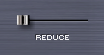
This controls the amount of Sample-Rate Reduction that is introduced to the Oscillator. By reducing the sample rate, distortion and artifacts called "aliasing" are introduced to the sound. Generally, aliasing is avoided in digital audio, but here it can be used in a controlled manner to add wildly different tonal qualities.
The higher this slider is set, the lower the sample rate, and the more pronounced the effect will be.
REDUCE is Modulatable.
Range 0.000 to 1.000
DEPTH

This controls the amount of Wave-Shaping that is introduced to the Oscillator. The higher this slider is set, the more pronounced the effect of the Wave Shaper would be.
DEPTH is Modulatable.
MIX
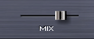
The mix mini-slider controls the balance between the original Oscillator’s signal and the Wave-Shaped sound. If the mix is at minimum setting, then the effect of the Wave Shaper is not heard. When set to maximum, only the Wave-Shaped signal is heard.
MIX is modulatable.
Range 0.000 to 1.000
TIP: Starting with simpler, less harmonically rich waveforms will produce the best results with the Wave Shaper.
NOTE: Polyphonic Wave-Shaping is powerful, but it takes significant CPU power, so use it wisely.
EDIT PAGE – Oscillator Wave Shaper Zoom
EDIT PAGE –
Oscillator Wave Shaper Zoom
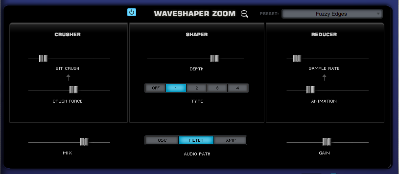
The Wave Shaper Zoom provides access to additional Wave-Shaping controls for more detailed and precise manipulation of your sound. This page is divided into three sections: CRUSHER, SHAPER, and REDUCER.
In the CRUSHER section, you can reduce the Bit-Depth using the BIT CRUSH slider to create digital distortion and you can make it more or less aggressive by using the CRUSH FORCE slider.
In the SHAPER section, you can control the amount of Wave-Shaping that is applied to your sound by using the DEPTH slider. You can also change the type of Wave-Shaping by selecting one of the four algorithms, which range from softer to more aggressive.
In the REDUCER section, you can reduce the sample rate by moving the SAMPLE RATE slider to create interesting alterations to the quality of the sound. By using the ANIMATION slider you can add a dynamic character that changes over time.
The Mix, Audio Path, and Gain Controls apply to all three sections.
WAVE SHAPER POWER SWITCH

This turns the Wave Shaping effect on or off.
WAVE SHAPER PRESETS

Wave Shaper Presets can be copied, pasted or saved from this menu.
EDIT PAGE – Oscillator Wave Shaper Zoom - Crusher
EDIT PAGE –
Wave Shaper - Crusher
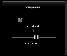
The CRUSHER section offers parameters for controlling the Bit Depth of the oscillator.
BIT CRUSH

Bit-crushing introduces distortion by reducing the resolution of digital audio. This lowers the dynamic range and increases the noise floor. Use this for achieving grainy or lo-fi sounds - it really adds character to your sound. The effect can range from slightly distorted to very harsh, depending on the slider setting.
BIT CRUSH is Modulatable.
Range 0.000 to 1.000
CRUSH FORCE

The Crush Force slider lets you add a unique distortion to the bit depth for a more aggressive sound. This parameter will have no effect if the BIT CRUSH slider is set to zero.
CRUSH FORCE is Modulatable.
Range 0.000 to 1.000
EDIT PAGE – Oscillator Wave Shaper Zoom - Shaper
EDIT PAGE –
Wave Shaper - Shaper
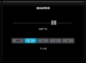
The SHAPER section offers controls for introducing Wave-Shaping to the oscillator.
DEPTH

In the SHAPER section, you can control the amount of Wave-Shaping that is applied to your sound by using the DEPTH slider. The farther to the right this is set, the more pronounced the effect of the Wave Shaper will be.
DEPTH is Modulatable.
Range 0.000 to 1.000
TYPE

You can change the type of Wave-Shaping by selecting one of the four preset Wave-Shaping algorithms. These range from softer to more aggressive - 1 being the most subtle and 4 the most extreme.
NOTE: Even with the Depth slider set to zero, there will be a certain amount of color added to the sound, so be sure to click the OFF button when Wave-Shaping is not in use.
EDIT PAGE – Oscillator Wave Shaper Zoom - Reducer
EDIT PAGE –
Wave Shaper - Reducer
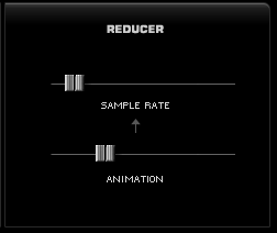
The REDUCER section offers parameters for controlling the Sample Rate of the oscillator.
SAMPLE RATE

This controls the amount of Sample-Rate Reduction that is introduced to the Oscillator. By reducing the sample rate, distortion and artifacts called "aliasing" are introduced to the sound. Generally, aliasing is avoided in digital audio, but here it can be used in a controlled manner to add wildly different tonal qualities. The higher this slider is set, the lower the sample rate, and the more pronounced the effect will be.
SAMPLE RATE is Modulatable.
Range 0.000 to 1.000
ANIMATION

The Animation slider adds a dynamic, time-variant character to the sound. This parameter will not have any effect if the SAMPLE RATE slider is set to zero.
ANIMATION is Modulatable
Range 0.000 to 1.000
EDIT PAGE – Oscillator Wave Shaper Zoom - Mix, Path and Gain
EDIT PAGE –
Wave Shaper - Mix, Path and Gain

MIX

The MIX slider controls the balance between the original Oscillator’s signal and the Wave-Shaped sound. If the mix is at the minimum setting, then the effect of the Wave Shaper is not heard. When set to the maximum, only the Wave-Shaped signal is heard.
MIX is modulatable.
Range 0.000 to 1.000
AUDIO PATH
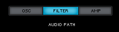
These three mode switches determine at what point in Omnisphere’s audio path that the Wave Shaper is placed. It can be placed after the Oscillator, the Filter or the Amplifier;
OSC (Oscillator) - The Wave Shaper is placed after the Oscillator output, before the Filter section.
FILTER (Filter) - The Wave Shaper is placed after the Filter’s output, before the Amplifier.
AMP (Amplifier) - The Wave Shaper is placed after Omnisphere’s Amplifier.
GAIN

The GAIN slider controls the amount of gain that is applied to the output.
Range 0.000 to 1.000
EDIT PAGE – Oscillator Voice Multiplyer
EDIT PAGE – Oscillator Voice Multiplier
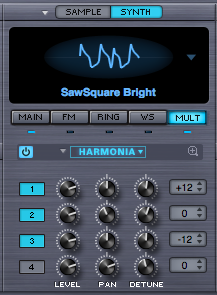
The MULT sub-page contains all the unique, polyphonic Voice Multiplier functions of Omnisphere. The Voice Multiplier adds richness and variety with three versatile modes; Polyphonic Unison, Granular Synthesis and Harmonia. All three modes work via the same basic principle of multiplying the number of oscillator voices to achieve different types of sonic enrichment.
The modes of the Voice Multiplier are exclusive;
meaning only one of these features can be active at a time. When the OSCILLATOR
is in SAMPLE mode, all three Voice Multiplier modes are available; GRANULAR,
HARMONIA and UNISON.
In SYNTH mode, only two of the Voice Multiplier
modes are available; HARMONIA and UNISON. However, the SYNTH Voice Multiplier
modes have some extra features not available in SAMPLE mode.
NOTE: The three Voice Multiplier functions; Unison, Granular and Harmonia, can be very CPU-intensive, so account for this when setting the Voice count and envelope Release times.
EDIT PAGE – Oscillator Unison
EDIT PAGE –
Oscillator Voice Multiplier - Unison
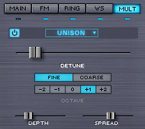
In vintage analog polyphonic synthesizers, Unison was used
to trigger all of the voices cards of the synthesizer at the same time for a
rich, detuned monophonic sound. Omnisphere
takes Unison to the next level by offering polyphonic Unison, with numerous enhancements and
controls. Just a few or many
unison voices can be added, so each note played will sound several voices -
each with different detune, spread and octave.
UNISON POWER SWITCH

This turns the Unison effect on and off to quickly compare
the sound with and without it.
UNISON PHASE CONTROL (SYNTH
mode only)
The Phase Control option is unique to the SYNTH mode. The Phase Control means the initial
phases of the Unison voices can be randomly spread across a range. The width of the range they are spread
is controlled by stepping through the five Phase Control options, which range
completely from In-Phase to 180° out of Phase. Perfectly in-phase produces results like digital
synthesizers. Out of phase
settings produce classic analog-like results.
UNISON DETUNE
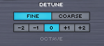
This determines to what degree the unison notes will be detuned
compared to the original OSCILLATOR. This setting does not affect the pitch of the original OSCILLATOR, just
the unison voices.
The Unison Detune control is modulateable.
UNISON DETUNE FINE/COARSE

These mode switches determine the range of the DETUNE
slider. If FINE is selected, then
the DETUNE slider will only detune the UNISON voices up to a half step (99
cents). This works for
classic Unison and “SuperSaw” types of sounds.
When COARSE is selected, the range of the DETUNE slider is
increased to a fifth or an octave above the note, depending how many are added.
When the Detune slide is used in COARSE mode, the Unison voices will gradually
glide to the final chord, producing the classic “THX” logo effect.
DETUNE OCTAVE
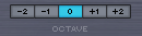
The Octave switches specify at which octave the unison notes
will sound, up to two octaves above or two octaves below. This is not a traditional transpose
control, as it only pitches the UNISON voices up or down – the pitch of
the Oscillator will still be at the same pitch.
UNISON DEPTH

The DEPTH slider controls the amount of UNISON voices
added. Increasing the setting of
this slider increases the number of UNISON voices. The more Unison voices used, the richer the sound, but the
higher the demand on the CPU.
The maximum number of Unison voices is eight.
UNISON SPREAD

UNISON voices can panned across the stereo image. Spread
controls the extent of the stereo imaging. When the mini-slider is at minimum setting, the UNISON
voices are all in the center of the stereo image. When set to maximum value, the UNISON voices are panned
across the stereo field.
Both the UNISON DEPTH and SPREAD are modulatable.
Range 0.000 to 1.000
EDIT PAGE – Oscillator Harmonia™
EDIT PAGE –
Oscillator Voice Multiplier - Harmonia™
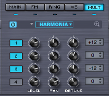
HARMONIA™ is one of Omnisphere’s most exciting and unique features. While it may seem like it shares the same functionality of the traditional Harmonizer effect, it’s actually far more powerful because it’s built into Omnisphere’s OSCILLATOR as a polyphonic synthesis component, and not just as an audio effect.
HARMONIA™ adds four additional oscillators to the layer. Since each Layer has it’s own HARMONIA section, it can add up to eight additional oscillators per patch, for a total of ten!
The HARMONIA™ section in the Edit Page has a basic set of parameters. The complete set of HARMONIA™ controls are available in the HARMONIA ZOOM page.
HARMONIA PRESETS
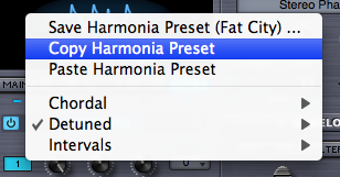
A complete set of HARMONIA presets can be accessed by
selecting the menu arrow. Any
factory presets can be copied, pasted or saved as well as any custom settings.
HARMONIA VOICES 1-4

Up to four HARMONIA voices can be stacked on top of the
OSCILLATOR’S voice by selecting the numbered switches in HARMONIA.
Keep in mind the more additional voices are added, the
higher the demand on the CPU.
HARMONIA LEVEL
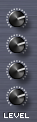
Controls output level of the HARMONIA voices, so the effect of each Harmonia voice can be subtle or pronounced. The HARMONIA LEVEL controls are modulatable.
Range 0.000 to 1.000
HARMONIA PAN
Each of the HARMONIA voices can be individually positioned
in the stereo field with the PAN controls.
Range 0.000 to 1.000
HARMONIA DETUNE
Each of the HARMONIA voices can be detuned by +/- 100 cents. When the knobs are centered, there is no detuning of the HARMONIA voices. The HARMONIA DETUNE controls are modulatable.
HARMONIA INTERVAL
Each of the HARMONIA voices can be transposed over a
four-octave range. Selecting the
INTERVAL switch will bring up a drop-down menu of half-step transpositions,
either up or down by two octaves.
Range -24 to +24
!
EDIT PAGE – Oscillator - Harmonia Zoom
EDIT PAGE –
Oscillator Voice Multiplier - Harmonia™ Zoom
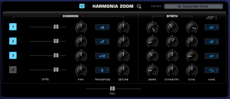
The Harmonia Zoom page contains all the Harmonia controls for each Layer. In addition to the controls available in the EDIT PAGE, it includes a MIX slider for balancing the original voice with the added voices and a set of controls that apply only to SYNTH oscillators.
EDIT PAGE – Oscillator - Harmonia Zoom - Controls
EDIT PAGE –
Oscillator Voice Multiplier - Harmonia™ Zoom Common Controls
HARMONIA POWER SWITCH

This turns HARMONIA on and off and is useful for comparing the sound with the added voices to the original sound.
HARMONIA PRESETS

A complete set of HARMONIA presets can be accessed by selecting the menu arrow. Any factory presets or custom settings can be copied, pasted or saved.
HARMONIA VOICES 1-4

Up to four HARMONIA voices can be stacked on top of the original voice by selecting the numbered switches in HARMONIA.
Keep in mind, adding more voices creates a higher demand on the CPU.
HARMONIA LEVEL

Controls the output level of the HARMONIA voices, so the effect of each Harmonia voice can be subtle or pronounced.
The HARMONIA LEVEL controls are modulatable.
Range 0.000 to 1.000
HARMONIA PAN

Each of the HARMONIA voices can be positioned in the stereo field with the PAN controls.
Range 0.000 to 1.000
HARMONIA DETUNE

Each of the HARMONIA voices can be detuned by +/- 100 cents. When the knobs are centered, there is no detuning.
The HARMONIA DETUNE controls are modulatable.
Range 0.000 to 1.000
HARMONIA INTERVAL

Each of the HARMONIA voices can be transposed over a four-octave range. Selecting the INTERVAL switch will bring up a drop-down menu of half-step transpositions, either up or down by as much as two octaves.
Range -24 to +24
HARMONIA MIX

This parameter controls the blend of the Harmonia voices with the primary voice.
The HARMONIA MIX parameter is modulatable.
Range 0.000 to 1.000
EDIT PAGE – Oscillator - Harmonia Zoom - Synth Controls
EDIT PAGE –
Oscillator Voice Multiplier - Harmonia™Zoom - Synth Controls
.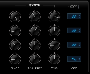
When the OSCILLATOR is set to SYNTH mode, all of the HARMONIA features in SAMPLE mode are available, as well as a second set of options that are unique to SYNTH mode. This special set of controls allows independent waveform control over each HARMONIA voice.
HARMONIA PHASE
Like the Phase Control option in UNISON, this is unique to the SYNTH Oscillators. The Phase Control allows the phase of the HARMONIA voices to be spread across a 180° range. The width of the range is controlled by stepping through the five Phase Control options, which range from In-Phase to totally Out-of-Phase.
HARMONIA SHAPE
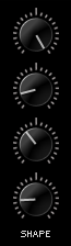
This control is unique to SYNTH Oscillators. This is an offset of the SHAPE control on the MAIN OSCILLATOR page. Each of HARMONIA’s four voices can have its own SHAPE offset. The center position indicates that the HARMONIA voice's SHAPE is identical to the main Synth Oscillator's SHAPE.
NOTE: To learn more about the SHAPE functionality, check out the description in the OSC MAIN chapter.
Range 0.000 to 1.000
HARMONIA SYMMETRY
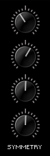
This control is unique to SYNTH Oscillators. This is an offset of the SYMMETRY control on the MAIN OSCILLATOR page. Each of HARMONIA’s four voices can have its own SYMMETRY offset. The center position indicates that the HARMONIA voice's SYMMETRY is identical to the main Synth Oscillator's SYMMETRY.
NOTE: To learn more about the SYMMETRY functionality, check out the description in the OSC SYMMETRY chapter.
Range 0.000 to 1.000
HARMONIA SYNC
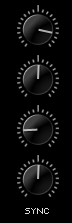
This control is unique to SYNTH Oscillators. This is an offset of the HARD SYNC control on the MAIN OSCILLATOR page. Each of HARMONIA’s four voices can have its own SYNC offset. The center position indicates that the HARMONIA voice's SYNC is identical to the main Synth Oscillator's HARD SYNC.
NOTE: To learn more about the HARD SYNC functionality, check out the description in the OSC HARD SYNC chapter
Range 0.000 to 1.000
HARMONIA WAVESHAPE
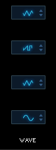
This control is unique to SYNTH Oscillators. The waveshape of each of the four HARMONIA voices can be set from these steppers. Four of the waveshapes are the same as those available in the Waveform Selector in OSC MAIN: Triangle, Sine, SawSquare Bright & SawSquare Fat. The fifth waveshape, called OSC, means the HARMONIA waveform will follow the primary Oscillator’s current waveform selection.

|
Triangle |
| |
|

|
Sine |
| |
|

|
OSC |
| |
|

|
SawSquare Fat |
| |
|
|
SawSquare Bright |
NOTE: To learn more about the SYNTH WAVESHAPE functionality, refer to the OSC SHAPE chapter
EDIT PAGE - Oscillator - Granular
EDIT PAGE –
Oscillator Voice Multiplier - Granular (Sample mode only)
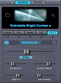
Granular synthesis is a powerful method of fragmenting pieces of sound into very small bits of audio called ‘grains’. Since each grain can have its own duration, amplitude and envelope, they can create a layered ‘soundscape’ of overlapping tones. The composer Innas Xenakis first conceptualized Granular synthesis in the 1970s.
Omnisphere contains a fully implemented set of granular controls. While only the most useful controls are presented on the Edit Page, the full set of Granular parameters is available on the Granular Zoom page. Soundsources turned into grains can be manipulated by altering their pitch, duration, envelope and position in the stereo field. Up to eight voices of granularity are available per Layer.
Granular Synthesis is a useful technique for creating a wide variety of sounds, like evolving soundscapes (using Grain and Pitch Controls), time stretching-type sounds (using Speed mode), "freezing" effects (using Position mode), or edgy, gritty glitchiness (using Intensity).
NOTE: Using Granular Synthesis can require a great deal of processing power, so use it wisely.
GRANULAR POWER SWITCH

This turns Granular on and off and it is useful for comparing the granulated sound with the original.
SPEED AND POSITION MODES

There are two exclusive Granular modes: SPEED and POSITION. While other granular parameters work in the same manner regardless of the mode, the slider above the SPEED and POSITION mode selectors controls only the mode selected.
When SPEED mode is selected, the SPEED slider controls the speed at which the grains progress through the sample. As the slider is moved to the right, it slows down the progress of the grains. At .5 (the center point), the grains stop moving through the sample causing a “freezing” effect. Above .5 it reverses and the grains go back towards the start of the sample. SPEED mode is relative: it governs where the next grains will play from relative to the current grains. For example, the grains will be able to move back towards the beginning of the sample only if a key has been depressed long enough to move past the beginning of the sample. Otherwise, you will only hear the beginning portion of sample being granulated. This mode is useful for creating time stretching-type effects, among other applications. The SPEED slider is modulatable.
When POSITION is selected, it is possible to select which portion of the sample is being granulated using the POSITION slider. As an example, you can choose to granulate only the "pluck," or only the decay of a guitar note. The number of zones in a Soundsource determines the maximum range of the POSITION slider. If the Soundsource has more than 12 zones mapped, the range of the POSITION slider slider is 1 second. If it has less than 12 zones, then the POSITION slider's range can be up to 90 seconds. This mode is useful for granulating a specific portion of the sample and for creating “freezing” effects. The POSITION slider is modulatable.
NOTE: Moving the SPEED and POSTION sliders while playing a sample will allow you to add a truly dynamic quality to the sound. Experiment with modulating and MIDI-Learning these parameters. Remember, these modes are exclusive, meaning you can use only one at a time.
In both modes, the results will vary depending on the settings of other Granular parameters, particularly INTENSITY, DEPTH, and SMOOTHING.
INTENSITY

When the sample is sliced into grains, the size of the grains can be altered, which changes the speed and INTENSITY of the effect. When the INTENSITY slider is lower, the grains are longer and there is a slower transition to the next grain. When the INTENSITY slider is higher, the grains are shorter and transition more quickly.
GRAIN Intensity is a Modulatable parameter.
Range 0.000 to 1.000
DEPTH

Moving this slider to the right increases the number of grains which are created from the Soundsource. The higher the number of grains, the higher the demand on the CPU. Excellent results can usually be obtained without using a lot of GRAIN DEPTH, so use it wisely.
Range 0.000 to 1.000
SMOOTHING

Since the grains can vary in pitch and amplitude, the change from grain to grain can be abrupt and jarring. Increasing the value of this slider softens the sharp transitions. Think of SMOOTHING as cross-fading between the grains.
Range 0.000 to 1.000
DETUNING

The grains can be detuned by increasing this control. The higher DETUNING is set, the more variation in pitch will be heard in the grains. This does not affect the pitch of the Soundsource itself, just the grains.
Range 0.000 to 1.000
EDIT PAGE - Oscillator - Granular Zoom
EDIT PAGE –
Oscillator Voice Multiplier - Granular Zoom
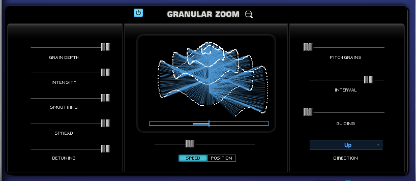
The Granular Zoom page contains an expanded set of Granular parameters for each Layer, providing more extensive Granular processing capabilities than those available in the Edit Page.
The Granular Zoom controls are enhanced with a dynamic Granular Visualizer, a 3D model that represents how the grains are manipulated in the STEAM engine.
The Granular Zoom page also includes the Pitch Grains Section, useful for creating grains that move dynamically through the pitch range.
GRANULAR POWER SWITCH

This turns Granular on and off and it is useful for comparing the granulated sound with the original.
GRANULAR VISUALIZER
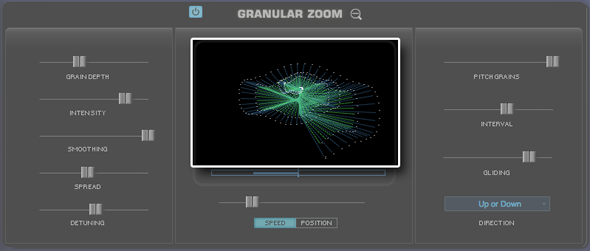
The Granular Visualizer is a dynamic 3D model that represents how the grains are manipulated in the STEAM engine. It provides visual feedback of the Granular parameters by changing colors, increasing the density and size of the spokes, adding waviness to the spiral, and adding a 3D appearance to it. This feedback can be very meaningful during the sound design process.
The parameters that affect the Granular Visualizer are GRAIN DEPTH, INTENSITY, SMOOTHING, SPREAD, DETUNING, PITCH GRAINS, INTERVAL, and GLIDING.
EDIT PAGE - Oscillator - Granular Zoom - Modes
EDIT PAGE –
Oscillator Voice Multiplier – Granular Zoom - Modes
There are two exclusive Granular modes: SPEED and POSITION. While other granular parameters work in the same manner regardless of the mode, the slider above the SPEED and POSITION mode selectors controls only the mode selected.
SPEED
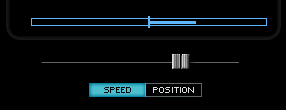
When SPEED mode is selected, the SPEED slider controls the speed at which the grains progress through the sample. As the slider is moved to the right, it slows down the progress of the grains through the sample. At .5 (the center point), the grains stop moving through the sample causing a “freezing” effect. Above .5 it reverses and the grains go back towards the start of the sample. SPEED mode is relative: it governs where the next grains will play from relative to the current grains. For example, the grains will be able to move back towards the beginning of the sample only if a key has been depressed long enough to move past the beginning of the sample. Otherwise, you will only hear the beginning portion of sample being granulated. This mode is useful for creating time stretching-type effects, among other applications. The blue bipolar display above the slider represents the speed and direction at which the grains will progress. The SPEED slider is modulatable.
POSITION

When POSITION is selected, it is possible to select which portion of the sample is being granulated using the POSITION slider. As an example, you can choose to granulate only the "pluck," or only the decay of a guitar note. The number of zones in a Soundsource determines the maximum range of the POSITION slider. If the Soundsource has more than 12 zones mapped, the range of the POSITION slider slider is 1 second. If it has less than 12 zones, then the POSITION slider's range can be up to 90 seconds. This mode is useful for granulating a specific portion of the sample and for creating “freezing” effects. The blue display above the slider represents the current position of the slider, hence the portion of the sample being granulated. The POSITION slider is modulatable.
NOTE: Moving the SPEED and POSTION sliders while playing a sample will allow you to add a truly dynamic quality to the sound. Experiment with modulating and MIDI-Learning these parameters. Remember, these modes are exclusive, meaning you can use only one at a time.
In both modes, the results will vary depending on the settings of other Granular parameters, particularly INTENSITY, DEPTH, and SMOOTHING.
Range 0.000 to 1.000
EDIT PAGE - Oscillator - Granular Zoom - Grain Controls
EDIT PAGE –
Oscillator Voice Multiplier - Granular Zoom - Grain Controls
GRAIN DEPTH

Moving this slider to the right increases the number of grains which are created from the Soundsource. The higher the number of grains, the higher the demand on the CPU. Excellent results can usually be obtained without using a lot of GRAIN DEPTH, so use it wisely. In the Granular Visualizer, GRAIN DEPTH adds more loops to the spiral, which represent more grains overlapping with each other.
Range 0.000 to 1.000
INTENSITY

When the sample is sliced into grains, the size of the grains can be altered, which changes the speed and intensity of the effect. When the INTENSITY slider is lower, the grains are longer and there is a slower transition to the next grain. When the INTENSITY slider is higher, the grains are shorter and transition more quickly. In the Granular Visualizer, INTENSITY increases the density of the spokes, to show shorter intervals.
GRAIN INTENSITY is a Modulatable parameter.
Range 0.000 to 1.000
SMOOTHING

Since the grains can vary in pitch and amplitude, the change from grain to grain can be abrupt and jarring. Increasing the value of this slider softens the sharp transitions. Think of SMOOTHING as cross-fading between the grains. In the Granular Visualizer, SMOOTHING changes the brightness of the blue lines.
Range 0.000 to 1.000
SPREAD

This slider controls the placement of the grains within the stereo image - the higher the SPREAD, the wider the grains will be panned across the stereo field. In the Granular Visualizer, SPREAD adds a 3D appearance to represent the added dimension.
Range 0.000 to 1.000
DETUNING

The grains can be detuned by increasing this control. The higher DETUNING is set, the more variation in pitch will be heard in the grains. This does not affect the pitch of the Soundsource itself, just the grains. In the Granular Visualizer, DETUNING adds a waviness to the spiral.
Range 0.000 to 1.000
EDIT PAGE - Oscillator - Granular Zoom - Pitch Controls
EDIT PAGE –
Oscillator Voice Multiplier - Granular Zoom - Pitch Controls
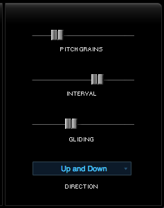
PITCH GRAINS

This slider sets how often the grains will be transposed in pitch. The PITCH GRAINS parameter and the ones below it, INTERVAL, GLIDING and DIRECTION menu, are interdependent. When the PITCH GRAINS parameter is set to 0, the INTERVAL, GLIDING nor DIRECTION parameters will have no effect. In the Granular Visualizer, PITCH GRAINS determines the percentage of lines which have an alternate color based on the INTERVAL setting.
The PITCH GRAINS parameter is modulatable.
INTERVAL

This slider determines what musical interval the PITCH GRAINS will use. The INTERVAL can be set from one to twelve semitones. This parameter will have no effect if the PITCH GRAINS slider is set to zero. In the Granular Visualizer, INTERVAL selects an alternate color for a percentage of lines determined by PITCH GRAINS.
Range 1 to 12 semitones
GLIDING

GLIDING determines how often the grains will glide between the note that is played and the transposed interval of a pitch grain. This parameter will have no effect if the PITCH GRAINS slider is set to zero. In the Granular Visualizer, GLIDING shortens a percentage of lines determined by PITCH GRAINS.
Range 0.000 to 1.000
DIRECTION

The items in the DIRECTION menu determine which direction the PITCH GRAINS are transposed.
There are four PITCH GRAIN DIRECTIONS available:

|
The PITCH GRAINS will be transposed up only. |
| |
|

|
The PITCH GRAINS will be transposed down only. |
| |
|

|
The PITCH GRAINS will be transposed up or down only – they will never be transposed up and down on the same note. |
| |
|

|
The PITCH GRAINS will be transposed randomly up and down on the same note. |
EDIT PAGE - Filters
EDIT PAGE - Filters
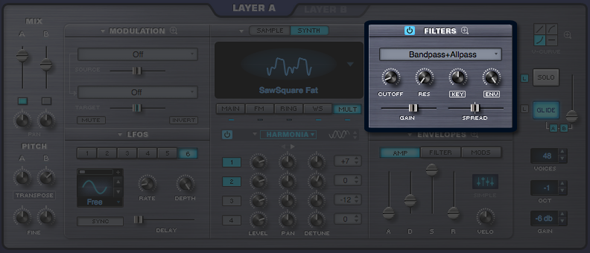
The Filter is a key component of subtractive
synthesis. It’s designed to remove
frequencies from within a sound, which can enhance the character of that
sound. Filters typically consist
of a cutoff control, which sets the removal of certain frequencies, and a
resonance control, which emphasizes the frequency of the cutoff point.
The most common form of filtering is called
lowpass, which means that higher frequencies are removed while lower
frequencies pass through
without being removed. Most vintage
synthesizers employed low-pass filtering, but some also included high-pass
filtering, which removes low frequencies and lets the high frequencies pass
through.
Omnisphere includes an exceptionally versatile
dual-filtering system, which features two stereo filters per layer that can be
routed in series or parallel. There are twenty-four different filter types available, which include
lowpass, highpass, bandpass and other specialized varieties. Because Omnisphere’s filters are
stereo, they are ideal for dynamic filter panning effects.
The FILTERS section of the EDIT overview features
a basic set of filter controls, such as Cutoff, Resonance, Keyboard tracking
and Filter envelope depth. The
full set of filter controls are available on the FILTER ZOOM view.
FILTER POWER SWITCH

Enables or disables the Filter.
NOTE: Turning the Filter OFF
saves CPU power, since every voice played has it’s own dual-filter per Layer.
FILTERS PRESETS
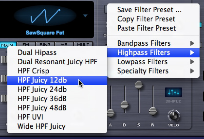
Omnisphere has a wide variety of customized
filter configurations, called presets. The presets represent the settings of Omnisphere’s complex dual stereo
filter. Filter presets can
be selected, copied, pasted and saved from this menu.
TIP: If you find a Patch that
has an interesting custom filter configuration, you can save it into your
preset library to use with your own patches!
The Presets are categorized into several
sub-categories; Bandpass Filters, Highpass Filters, Lowpass Filters and Specialty Filters. For the sake of space, the preset names
are abbreviated, but this is what the different abbreviations mean;
BPF |
Band Pass Filter |
HPF |
High Pass Filter |
LPF |
Low Pass Filter |
UVI |
UVI Filter from Atmosphere® |
db |
Short for Decibel. Names like 12db, 24db, refer to the roll off slope of the filters. |
NOTE: Filter presets are not the
same as Filter types. Filter
Presets include the settings for Filter type. Filter types are covered in the FILTER ZOOM section.
FILTER PRESET MENU
After a Preset has been chosen from the drop-down
menu, the name will be displayed in the preset display window:

If the filter types are changed in the Zoom view,
then the display will be changed to “Modified” until the Filter settings are
saved as a preset or another preset is selected.

NOTE: Filter presets
intentionally do not recall CUTOFF, RES, KEY and ENV settings. This is done
because it’s the best way to audition the different Filter Presets within the
context of your current Patch.
EDIT PAGE - FIlter Cutoff
EDIT PAGE - FIlter Cutoff

The
primary function of the filter is to remove, hence "cut off",
frequencies from the sound. Omnisphere’s
filter can remove frequencies in a variety of ways, from Lowpass, Highpass,
Bandpass, Notch and also specialized filter types. When different Types are loaded, the Cutoff will
remove different frequencies from the sound.
Depending what Filter preset is chosen, the Cutoff control
will remove different frequencies in various ways.
For example, if a Low Pass filter is used, turning the
control counter-clockwise will remove the higher frequencies. If a High-Pass Filter is used, the
opposite will happen. It’s best to
experiment with cutoff control with the wide variety of Filter Types.
The Filter’s roll off slope is measured in dB, and is
sometimes expressed in “poles”. The higher the dB value, the greater the extent of the filtering, but
this should not be confused with sounding “better”. Filters with fewer poles can often sound more appropriate
than those with more poles.
6dB = |
1 Pole |
12dB = |
2 Pole |
18dB = |
3 Pole |
24dB = |
4 Pole |
Range 00.05Hz to 19.00kHz
EDIT PAGE - FIlter Resonance
EDIT PAGE - FIlter Resonance

Resonance is also called ‘Q’ or
Emphasis in synthesizers, because it emphasizes the cutoff point of the
filter. Resonance can often
increase the loudness of the Filter, so its a good idea to use this control
along with the Filter Gain, so that audio clipping does not occur.
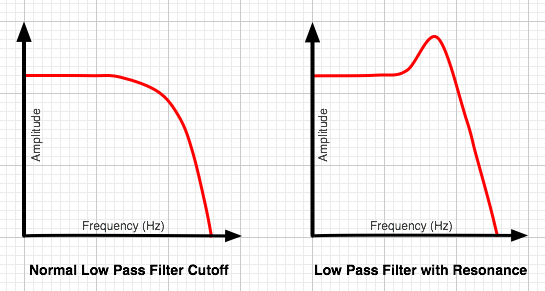
TIP:
Omnisphere’s UVI1 filter can self-oscillate. If the Resonance is set to maximum, the filter can be
‘tuned’ by the cutoff control.
EDIT PAGE - Filter Key Tracking
EDIT PAGE - Filter Key Tracking

The Filter Tracking is a dedicated
modulation control. It determines
to what extent the cutoff frequncy will track the keyboard. The higher the KEY value is set, the
more the filter will open over the upper range of the keyboard and close in the
lower ranges of the keyboard.
For example, if a low pass filter
is loaded and the cutoff is set below 1.00KHz, the notes played below middle-C
will become increasingly darker in tone, and keys above middle-C will be
increasingly brighter. At
the minimum setting, higher and lower notes have no effect on the cutoff
frequency.
Range 0 to 127
FILTER KEY TRACKING INVERT SWITCH

Key Tracking can be inverted simply
by selecting the word “Key” below the control. This switch will change to inverted text when Key tracking
is inverted and the sonic result will be the opposite of standard Filter Key
Tracking.
EDIT PAGE - Filter Envelope Depth
EDIT PAGE - Filter Envelope Depth

The Filter Envelope Depth is a
dedicated modulation control. It
sets the amount that the Filter Envelope controls the cutoff frequency. At minimum setting, the Filter Envelope
has no affect on the cutoff. The
higher the setting, the greater effect the Filter Envelope’s contour has in opening
and closing the Filter.
NOTE – If both the Filter
Cutoff and Filter Envelope Depth are set to minimum values, little to no sound
will be heard. If the Filter
Cutoff is at the maximum value, then the ENV DEPTH knob will have no effect,
since the cutoff is already wide open. A good starting point is to keep the ENV
control at the middle point.
Range 0 to 127
ENV INVERT SWITCH

This control inverts the Filter
Envelopes contour and so it will have the effect of closing the filter
(lowering the cutoff frequency). This switch will change to inverted text when
Env tracking is inverted.
TIP: Inverting the Filter’s Envelope can be useful for creating
unusual contours, such as double triggering and release effects
EDIT PAGE - Filter Gain and Spread
EDIT PAGE - Filter Gain & Spread
GAIN

By default the FILTER GAIN is set
at 0.0db. Changing this control
alters the output level of the Filters. One application would be if the Filter is closed down, and the tone is
quite dark and rather low in output, the level could be compensated for by
using the FILTER GAIN control. More commonly, Filter combinations with Resonances can get too loud,
causing distortion and clipping. The GAIN slider is very useful to reduce the overall level in these
cases.
Range between - inf (0) and
+9.54.dB
SPREAD

The SPREAD control in Omnisphere’s
Filter is not typically found on most synthesizers. Since Omnisphere’s filter is stereo, the SPREAD control can
move the cutoff frequency in one direction on one side of the stereo field
while moving it in the opposite direction in the other side of the stereo
field.
For example, the filter would be
opening on the right channel while closing on the left channel. This can create unique panning effects
that are more dramatic than the standard audio panning approach –
particularly when SPREAD is modulated.
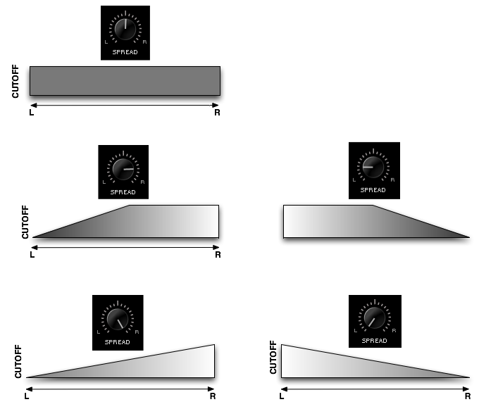
NOTE: Unlike the other filters, the Power filter is not a pair of L/R mono filters. Instead, it's a stereo filter with no spread capability. In the case of the Power Filter, the Spread control does the same function as the Width control in the Power Filter effect unit.
EDIT PAGE - FIlter Zoom
EDIT PAGE - FIlter Zoom
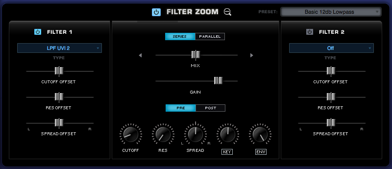
FILTER ZOOM in Omnisphere provides precise control over each
Layer’s dual-filter. The two
stereo filters are represented on the right and left. The central area controls
the routing and contains the shared controls. Each of the two stereo filters can have any of 24 filter
types assigned to it. They can be
combined in series or parallel, allowing for hundreds of possible filter
configurations.
There are primary Cutoff and Resonance controls for the
entire filter, but both FILTER 1 and FILTER 2 each have their own independent
Cutoff and Resonance offsets which are applied to those primary values.
Dual-Filter Power Switch

Enables or disables the entire Filter. It is a duplicate of the power button
on the EDIT page. The entire Dual-Filter can be turned on and off with this
switch, which provides a quick way to compare the sound with and without
filtering.
FILTER 1 & FILTER 2 Power Switches


Enables or disables Filter 1 and/or Filter 2.
NOTE: If both Filter 1 and
Filter 2 are turned off, the only control on the Filter Zoom page that will
still change the sound is the GAIN slider.
FILTERS PRESETS
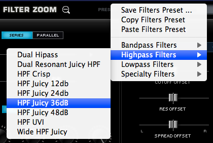
Omnisphere has a wide variety of customized
filter configurations, called presets. The presets represent the settings of Omnisphere’s complex dual stereo
filter. Filter presets can
be selected, copied, pasted and saved from this menu.
TIP: If you find a Patch that
has an interesting custom filter configuration, you can save it into your
preset library to use with your own patches!
The Presets are categorized into several
sub-categories; Bandpass Filters, Highpass Filters, Lowpass Filters and Specialty Filters. For the sake of space, the preset names
are abbreviated, but this is what the different abbreviations mean;
BPF |
Band Pass Filter |
HPF |
High Pass Filter |
LPF |
Low Pass Filter |
UVI |
UVI Filter from Atmosphere® |
db |
Short for Decibel. Names like 12db, 24db, refer to the roll off slope of the filters. |
NOTE: Filter presets are not the
same as Filter types. Filter
Presets include the settings for Filter type.
FILTER PRESET MENU
After a Preset has been chosen from the drop-down
menu, the name will be displayed in the preset display window:

If the filter types are changed in the Zoom view,
then the display will be changed to “Modified” until the Filter settings are
saved as a preset or another preset is selected.

NOTE: Filter presets
intentionally do not recall CUTOFF, RES, KEY and ENV settings. This is done
because it’s the best way to audition the different Filter Presets within the
context of your current Patch.
FILTER ZOOM - Structure
FILTER ZOOM –
Structure
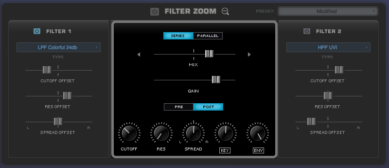
The central part of the FILTER ZOOM section is dedicated for
controls that are common to both of the Filters, including the ability to route
to two Filters in parallel or in series and to place them before or after the
Amplifier.
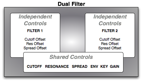
Aside from the Series/Parallel and Mix option, the remaining
four knobs (CUTOFF, RES, SPREAD, KEY, ENV) are exactly the same as those in the
Filter section on the EDIT page. So any changes that are made on these controls will be reflected on the
Edit page as well.
SERIES/PARALLEL

When Omnisphere’s two Filters are in “Series”, it means that
the output of Filter 1 is feeding into Filter 2 – and thus affects the
character of Filter 2. When the
two Filters are in Series, the Mix control is not in use. “Parallel“ means the two Filters are
both working, but they are not directly affecting the other; they are operating
side-by-side and mixed together. The Mix slider controls the balance between the two filters.
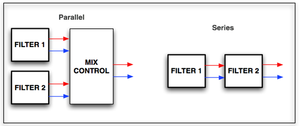
MIX

In Parallel mode, each of the two Filters pass thru the
Filter Mixer, and the Mix control determines how much of each filter is
heard. Centering the slider will
allow both filters to be heard equally, and sliding it to the right or left
will favor one over the other.
Range 100.00 to 00.100 (50.50 is the center
point)
GAIN

The Gain adjusts the level of the input, or output of the
Filter Module.
Range between - inf (0) and +9.54.dB
PRE & POST

The Dual-Filter can be placed before or after the Gain
Control. These switches determine
if the gain control will be used before or after the Filter. Aggressive Filter sounds will have a
different character depending if PRE or POST is enabled.
PRE
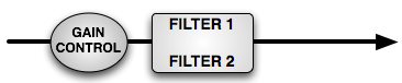
The Gain Control is applied before the Filters.
POST
POST means that the Gain Control will be applied after the
Filters
FILTER ZOOM - Filter Type
FILTER ZOOM
– Filter Type

The Filter Type menu allows you to select the actual Filter
algorithm to be used in Filter 1 or Filter 2. Omnisphere comes with a wide range of filter types. Each of the two stereo filters has the
same twentyfour filter types available.
Because of the flexible dual-filter system in Omnisphere,
these different filter types can be combined, routed in series or parallel,
allowing for hundreds of possible filter configurations.
The extent to which the frequencies are removed is based on
the roll-off slope (measured in dB) of the filter type. This means a Lowpass filter with a 24dB
roll-off is going to allow less sound to pass through than a filter with a 12dB
roll-off.
Once a customized filter configuration has been created, the
settings can be saved as a Filter Preset and loaded it from the FILTERS section
on the EDIT overview page.
OFF |
|
The Filter is off. |
| |
|
|
LOW PASS |
Gentle 6db |
A subtle, 1-pole low pass, useful for acoustic sounds |
| |
Crisp 12db |
|
| |
Warm 12db |
|
| |
Juicy 12db |
This new 2-pole Low Pass filter has a very smooth response at high resonances. |
| |
Warm 24db |
|
| |
Smooth 24db |
|
|
Colorful 24db |
|
|
Edge 24db |
|
|
Juicy 24db |
This new 4-pole Low Pass filter has a very smooth response at high resonances. |
|
Power LP24 |
This is the Low Pass 24db filter from the Power Filter FX module |
| |
UVI 1 |
The 4-pole 24db Low Pass filter used in Atmosphere (can
self-oscillate) |
| |
UVI 2 |
The 3-pole 18db Low Pass filter used in Atmosphere |
| |
UVI 3 |
The 2-pole 12db Low Pass filter used in Atmosphere |
| |
|
|
HIGH PASS |
UVI |
The 2-pole 12db High Pass filter used in Atmosphere |
| |
Crisp |
|
| |
Juicy 12db |
This new 2-pole High Pass filter has a very smooth response at high resonances. |
| |
Juicy 24db |
This new 4-pole High Pass filter has a very smooth response at high resonances. |
| |
|
|
OTHER |
Bandpass |
All frequencies above and below a certain range are
removed. |
| |
Bandpass Juicy 12db |
This new 2-pole Band Pass filter has a very smooth response at high resonances. |
| |
Bandpass Juicy 24db |
This new 4-pole Band Pass filter has a very smooth response at high resonances. |
| |
Notch |
Frequencies pass thru a narrow ‘notch’, also known as a
‘band-reject’ filter |
| |
Allpass |
All frequencies are passed equally, but it changes the
phase relationship between the frequencies. |
| |
Metal Pipe + |
A complex stereo comb-filter that produces flanger-like
metallic overtones |
| |
Metal Pipe - |
A complex stereo comb-filter, inverted |
FILTER ZOOM - Offsets
FILTER ZOOM –
Offsets
CUTOFF OFFSET

The Filter Cutoff settings affect both FILTER 1 and FILTER
2. The CUTOFF OFFSET
counterbalances the Cutoff for FILTER1 and FILTER2 independently. These are not separate filters
controls; they simply increase or decrease the Cutoff frequency of that
particular Filter Type, relative to the primary Cutoff control.
When the slider is centered in the middle, there is no
offset to the Filter Cutoff. Moving the control to the right increases the Filter Cutoff and moving
it to the left decreases the cutoff.
RESONANCE OFFSET

As Filter Resonance settings affect both FILTER 1 and FILTER
2, the RES OFFSET (meaning Resonance Offset) allows the depth of the resonance
for FILTER1 and FILTER2 to be set independently. This control decreases or increases the amount of Resonance
of that particular Filter Type.
When the slider is centered in the middle, there is no
offset to the Filter Resonance. Moving the slider to the right increases the Filter Resonance and
setting it farther left decreases the Resonance.
SPREAD OFFSET

As both of Omnisphere’s filters are stereo, they are both
capable of offsetting their stereo position with this control. Like the other Offset controls in
Filter Zoom, this counterbalances the setting of the primary control, in this
case is the Spread control.
NOTE: Since Spread moves the
cutoff between Right and Left, the Spread Offset can counteract the Spread’s
setting for each Filter if moved in the opposite direction
FILTER ZOOM - Cutoff
FILTER ZOOM -
Cutoff

The primary Cutoff control is identical to the Cutoff
control on the EDIT page. The
primary function of the filter is to remove, hence "cut off",
frequencies from the sound. Omnisphere’s
filter can remove frequencies in a variety of ways, from Lowpass, Highpass,
Bandpass, Notch and also specialized filter types. When different Types are loaded, the Cutoff will
remove different frequencies from the sound.
Depending what Filter preset is chosen, the Cutoff control
will remove different frequencies in various ways.
For example, if a Low Pass filter is used, turning the
control counter-clockwise will remove the higher frequencies. If a High-Pass Filter is used, the
opposite will happen. It’s best to
experiment with cutoff control with the wide variety of Filter Types.
The Filter’s roll off slope is measured in dB, and is
sometimes expressed in “poles”. The higher the dB value, the greater the extent of the filtering, but
this should not be confused with sounding “better”. Filters with fewer poles can often sound more appropriate
than those with more poles.
6dB = |
1 Pole |
12dB = |
2 Pole |
18dB = |
3 Pole |
24dB = |
4 Pole |
Range 00.05Hz to 19.00kHz
FILTER ZOOM – Resonance
FILTER ZOOM –
Resonance

The Resonance control on the FILTER ZOOM page is identical
to the RES knob on the EDIT page. Resonance is also called ‘Q’ or Emphasis in
synthesizers, because it emphasizes the cutoff point of the filter. Resonance can often increase the
loudness of the Filter, so its a good idea to use this control along with the
Filter Gain, so that audio clipping does not occur.
TIP: Omnisphere’s UVI1 filter can self-oscillate. If the Resonance is set to maximum, the
filter can be ‘tuned’ by the cutoff control.
Range 0 to 127
FILTER ZOOM - Spread
FILTER ZOOM -
Spread

The SPREAD control on the FILTER ZOOM page is identical to
the SPREAD slider on the EDIT page. The SPREAD control in Omnisphere’s Filter
is not typically found on most synthesizers. Since Omnisphere’s filter is stereo, the SPREAD control can
move the cutoff frequency in one direction on one side of the stereo field
while moving it in the opposite direction in the other side of the stereo
field.
For example, the filter would be opening on the right
channel while closing on the left channel. This can create unique panning effects that are more
dramatic than the standard audio panning approach – particularly when
SPREAD is modulated.
Range L to R
NOTE: Unlike the other filters, the Power filter is not a pair of L/R mono filters. Instead, it's a stereo filter with no spread capability. In the case of the Power Filter, the Spread control does the same function as the Width control in the Power Filter effect unit.
FILTER ZOOM – Key Tracking
FILTER ZOOM – Key Tracking

The KEY control on the FILTER ZOOM page is identical to the
KEY slider on the EDIT page. The Filter Tracking is a dedicated modulation
control. It determines to what
extent the cutoff frequency will track the keyboard. The higher the KEY value is set, the more the filter will
open over the upper range of the keyboard and close in the lower ranges of the
keyboard.
For example, if a low pass filter is loaded and the cutoff
is set below 1.00KHz, the notes played below middle-C will become increasingly
darker in tone, and keys above middle-C will be increasingly brighter. At the minimum setting, higher
and lower notes have no effect on the cutoff frequency.
KEY INVERT SWITCH

The KEY INVERT switch on the FILTER ZOOM page is identical
to the KEY INVERT switch on the EDIT page. Key Tracking can be inverted simply
by selecting the word “Key” below the control. This switch will change to inverted text when Key tracking
is inverted and the sonic result will be the opposite of standard Filter Key
Tracking.
FILTER ZOOM - Envelope
FILTER ZOOM -
Envelope

The Filter ENV control is identical to the ENV control found
on the EDIT page. The Filter
Envelope Depth is a dedicated modulation control. It sets the amount that the Filter Envelope controls the
cutoff frequency. At minimum
setting, the Filter Envelope has no affect on the cutoff. The higher the setting, the greater
effect the Filter Envelope’s contour has in opening and closing the Filter.
NOTE – If both the
Filter Cutoff and Filter Envelope Depth are set to minimum values, little to no
sound will be heard. If the Filter
Cutoff is at the maximum value, then the ENV DEPTH knob will have no effect,
since the cutoff is already wide open. A good starting point is to keep the ENV
control at the middle point.
ENV INVERT SWITCH

The Filter ENV INVERT switch is identical to the Filter ENV
INVERT switch on the EDIT page. This control inverts the Filter Envelopes contour and so it will have
the effect of closing the filter (lowering the cutoff frequency). This switch
will change to inverted text when Env tracking is inverted.
TIP: Inverting the Filter’s Envelope can be
useful for creating unusual contours, such as double triggering and release effects
EDIT PAGE - Envelopes
EDIT PAGE - Envelopes
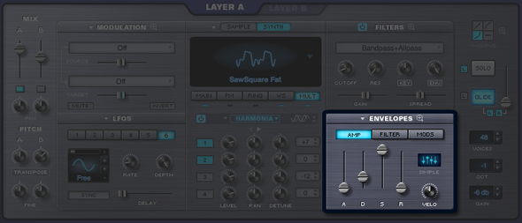
One of the innovative features of Omnisphere's envelopes is that each of them has two interfaces. There have always been two competing design philosophies; ADSR envelopes, which are fast and easy to use, and Complex envelopes, which are more powerful and flexible but typically not as fast or easy to use.
In Omnisphere we combined both ideas into one, offering the best of both worlds. Omnisphere's envelopes are extremely powerful and at the same time very easy to use, regardless of the envelope style.
Envelopes are the contours that shape the sound coming from the Oscillators and the Filters.
A basic ADSR-style envelope determines how quickly a sound will begin, its initial decay, what level it sustains at, and how long it will fade out after the note has been released. These different elements of the envelope are called stages. Most synthesizers have 4-stage envelopes, often called ADSR envelopes, which stands for Attack, Decay, Sustain and Release.
Complex envelopes contain contours with more than four stages. Complex envelopes allow a much greater degree of control in shaping the sound, and offer tremendous flexibility when shaping sounds and can be very useful in creating rhythmic shapes.
Each Part in Omnisphere has eight envelopes, and each can be used either as a basic 4-stage ADSR envelope, or as a Complex envelope. Each Layer has a dedicated AMP (Amplitude) envelope and a dedicated FILTER envelope, while there are four Modulation envelopes that are common to both Layers.
AMP ENVELOPE
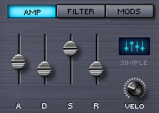
Each Part has two dedicated AMP (Amplitude) Envelopes, one each for Layer A and Layer B. These shape the overall loudness of the Layer. A dedicated Velocity knob controls the dynamic output of the AMP Envelopes based on MIDI Velocity.
FILTER ENVELOPE
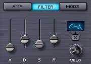
Each Part also has two dedicated FILTER Envelopes, one each for Layer A and Layer B. These shape the Filter cutoff for each Layer. A dedicated Velocity knob controls the dynamic output of the FILTER Envelopes based on MIDI Velocity.
MODULATION ENVELOPES
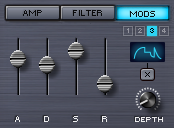
Modulation Envelopes are global, meaning there are a total of four Mod Envelopes available per Part. The Modulation Envelopes are monophonic, in contrast to the FILTER and AMP envelopes, which are polyphonic. The best way to think of Modulation Envelopes is as uni-polar LFOs that can have custom defined shapes.
1, 2, 3, 4 (Modulation Envelope buttons)

Under the MODS sub-page these small switches select any of the four modulation envelopes.
Instead of a dedicated VELO (Velocity) control, each of the four Modulation Envelopes has its own DEPTH control knob.
EDIT PAGE – ADSR Controls
EDIT PAGE – ADSR Controls
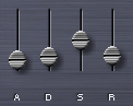
The ADSR Envelope slider interface operates the same way for all the different envelope types in Omnisphere.
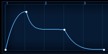
The screenshot above is from the Envelopes Zoom page, but illustrates what a standard ADSR Envelope looks like. The first to second point (or Stage) is the Attack time; the second point is the decay time, which ends at the third point, the Sustain level. After the note is released, the Sustain level drops away based on the Release time.
When viewed on the MAIN page, the ADSR looks like this;
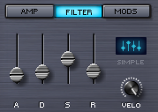
A - Attack

The ‘A’ stands for ATTACK, which means the attack time of the envelope. At minimum setting, the Attack is immediate, so the Envelope will start as soon as a controller triggers it. Higher settings will delay the Attack time, so the Envelope will gradually fade in.
Range between 0 to 20 seconds.
D - Decay

The ‘D’ is the DECAY time, which begins after the Attack has reached its maximum level. At minimum settings, the Decay will be zero, which means there is no Decay after the Attack and the Envelope goes straight to the Sustain stage. At the maximum setting, the DECAY can be about twenty seconds before the Sustain stage starts.
Range between 0 to 20 seconds
S - Sustain

‘S’ is the Sustain Level. Unlike A, D & R, Sustain is not a time value; it's a level value. Sustain determines at what level the Envelope’s output remains constant while a note is held. At the minimum setting there is no sustain, so the envelope’s output will stop until it’s been retriggered. Higher sustain settings mean the Envelope’s output will be constant as long as a note is held down.
R - Release

‘R’ is the Release time value. After a note has been let go, the sound will continue to decay for the duration of the Release time. Raising this fader lengthens the Release time. Lowering it decreases Release time.
Range 0 to 20 seconds.
ENVELOPE TYPES


Since each Envelope is capable of having either simple or complex contours, Omnisphere displays the status of the envelope shape with two icons:
The Simple icon looks like the four ADSR sliders, and will be displayed as long as the envelope has only 4 stages.
When an envelope has more than 4 stages, its icon will change to display the Complex icon, which looks like a Complex envelope, and includes an “X” button.
X BUTTON

When the X button is selected, it will revert the complex envelope contours to a SIMPLE one, and the icon will revert to the SIMPLE icon.
When you want to simplify an envelope, you can use the X button to quickly reset a complex envelope to a simple ADSR style envelope. This can’t be undone, so use it with caution!
NOTE: Changing an Envelope’s shape to complex can only be done by accessing the Envelope Zoom page and adding stages/points.
ENVELOPE DEPTH

The DEPTH controls are dedicated to the four MOD Envelopes. Turning this knob clockwise increases how much of the modulation envelope is sent to the modulation target. The default setting is at maximum.
NOTE: The DEPTH controls for the Modulation Envelopes are independent. The DEPTH control will only affect the selected envelope.
VELO (ENVELOPE VELOCITY)

VELO is short for Velocity Sensitivity. The Velocity knob controls how much MIDI velocity will affect the output signal of the Envelope. Moving the control counter-clockwise decreases the dynamic sensitivity of the envelope and clockwise changes increases the sensitivity.
NOTE: Each of the VELO (Velocity) controls for the two AMP and two FILTER envelopes are independent. The VELO control will only affect the selected envelope.
EDIT PAGE – Envelopes Zoom
EDIT PAGE – Envelopes Zoom
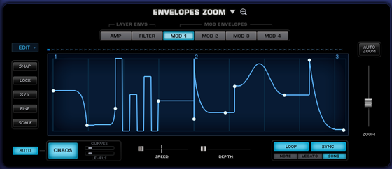
The ENVELOPE ZOOM page provides precise editing of the eight available envelopes in a Part. Complex envelopes can be created with hundreds of stages. Each envelope segment can have one of nine different curve presets applied to it. These include bumps, spikes, pulses, curves and linear transitions. It is not necessary to choose between a simple or complex envelope, since they both exist simultaneously. Any changes made to the ADSR sliders on the MAIN page will be reflected on the Envelopes Zoom page.
A complex envelope can be further configured via a dedicated set of editing options that can fine-tune, scale and modify specific parts of the envelope. Envelope contours can be repeated or ‘unrepeated’ to easily add or remove more stages.
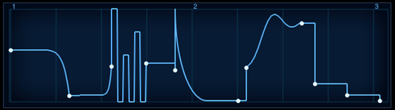
Envelope Zoom has a special CHAOS feature, which can randomize the envelope’s shape. Chaos can also be set to automatically change on every cycle, creating constantly changing envelopes. The degree that CHAOS will affect the Envelope is determined with dedicated probability mini-sliders.
You can also create a Groove Lock™ envelope simply by dragging and dropping a standard MIDI file (for example, from Stylus RMX) onto the Envelope Display. This will automatically create a rhythmic envelope matching the groove contained in the MIDI file.
EDIT PAGE – Envelopes Zoom Preset Menu
EDIT PAGE – Envelopes Zoom Preset Menu
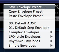
There are two drop-down menus that provide access to Envelope Presets. One is on the Edit Page next to the ENVELOPES label, the other is found in the Envelopes Zoom View beside the ENVELOPES ZOOM label.
The Drop-down menus will display a list of various Envelope presets as well as options to Save, Copy and Paste Envelopes.
Envelope Presets contain all the contours of a single envelope. The Save Envelope Preset function allows you to save envelopes for later recall. Envelopes can be copied to other Layers or Parts using the Copy/Paste Envelope Preset functions. This provides a quick and convenient way to work with envelopes, and Omnisphere ships with a large number of interesting and useful Envelope Presets for you to explore.
Saving & Loading Envelope Presets
To save a customized Envelope setting select Save Envelope Preset. A standard save dialogue will appear. Make sure that the preset that’s being saved is given a name. Omnisphere will automatically add the ‘.env’ extension to the name.
By default the Envelope preset will be saved in the STEAM folder, inside the Omnisphere Settings Library/Presets/Envelope folder. You can also create custom sub-folders within the Envelope folder to organize custom Presets according to your own preferences.
After a new Preset has been saved it can be loaded using the Envelope Presets menu. Use one of the drop-down menus and browse to your newly saved Preset.
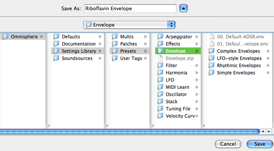
NOTE: In order to load any
shared Preset file, it must first be placed in the Envelope folder;
STEAM/Omnisphere/Settings
Library/Presets/Envelope/Sub-Folder
Only then will it appear on the
list of presets.
Copying & Pasting Envelope Presets
Select “Copy Envelope Preset” from the Presets menu to copy the current Envelope contours. Then select the Envelope to copy it to. This can be any of the Envelopes in the current Part - or in any other Part. From the Presets menu select “Paste Envelope Preset” and the copied Envelope will replace it.
NOTE: There is no ‘Undo’ for
Pasting an Envelope, so use caution when Copying and Pasting them.
EDIT PAGE – Envelopes Zoom Page Buttons
EDIT PAGE – Envelope Page Buttons
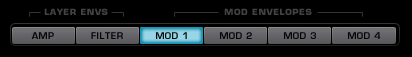
Above the Envelope Display area are six buttons that select the controls for the six Envelopes available in the current Layer.
NOTE: the AMP and FILTER Envelopes displayed are only for the current Layer, the other Layer must be selected to see the other two AMP/FILTER envelopes.
EDIT PAGE – Mod Envelopes Timeline
EDIT PAGE – Mod Envelopes Timeline

The four MOD Envelopes each have an LED indicator that tracks the time it takes to play through the Envelope contour. The rate of the Envelope’s contour will make these LEDs trace along as a visual guide. The LED timeline display is also helpful in monitoring the different types of Envelope triggering.
For example, if “NOTE” triggering is enabled, the LED display will start at the beginning of the Envelope every time a note is triggered. If “LEGATO” is selected, the LEDs will continue to along the timeline even when new legato notes are triggered.
NOTE: Until a MOD envelope has been set up as a modulation source to a target in Omnisphere, the LED display will be off.
EDIT PAGE – Envelopes Zoom Edit
EDIT PAGE – Envelopes Zoom Edit

There are four different automated Envelope adjustments, which provide a simple way to double and/or half the total number of Envelope points. These options can quickly change the playback rate of the Envelopes as well.
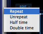
Repeat |
Every time ‘Repeat’ is selected, all of the stages in the Envelope will be duplicated, doubling the number of points. |
| |
|
Unrepeat |
Can undo any Repeats that have been done. Unrepeat can also be used to “halve” the number of segments in an envelope. |
| |
|
Half time |
Each time this is selected, Half time will change the speed of the Envelope’s contour by half. |
| |
|
Double time |
The speed of the Envelope’s contour will double every time this is selected. |
EDIT PAGE – Envelopes Zoom Display
EDIT PAGE – Envelope Display
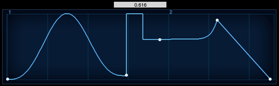
The contour of the current Envelope can be modified from this display. The point to the extreme left is always the Attack time and on the last two points on the right are the Sustain level and the Release time stages. Time is represented horizontally and Level is on the vertical axis.
To add an additional stage to the Envelope, right-click (Control-Click) and select "add" from the pop-up menu. When an additional point is added, all points to the right are shifted to make room for the new stage. When selecting between two points, a new point is inserted in the middle of the stage and the points to the right are not shifted.
Selecting and dragging any point in the display will change the position of the point. Selecting anywhere there is no line or point will move the background grid forward and back.
When any point has been selected a small numerical window will appear above the display that indicate the level settings for that point (0.000 is minimum and 1.000 is maximum).
Right Clicking (or Control-Clicking) in the display area will bring up the Envelope Curves menu, which is explained next.
EDIT PAGE – Envelopes Curves
EDIT PAGE – Envelope Curves
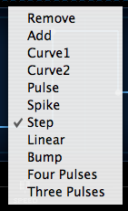
All of Omnisphere’s eight dedicated Envelopes are capable of generating contours with hundreds of points. Right/Control-clicking anywhere in the Envelope display are will bring up a list that allows points to be added or removed, followed by a list of preset curves.
Clicking and dragging directly on the curve can change the orientation and position of the curves. A cross hair will appear that will move the curve in any direction within the limits of the curve.
Some presets automatically have maximum level settings, such as Spike, Pulse and Bump. To reduce the levels, click and drag and the cross hair will appear that will allow the amplitude of the curve to be changed.
Remove |
|
Deletes the currently selected point |
| |
|
|
Add |
|
Puts a new point at the place in the Envelope
display. |
| |
|
|
Curve1 |

|
A gradual slope between the points |
| |
|
|
Curve2 |
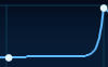
|
A steeper, more exponential slope between the
points. |
| |
|
|
Pulse |
|
Places a three-angle pulse shape between two
points. |
| |
|
|
Spike |
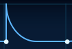
|
A sharp point with a gradual slope on one side. |
| |
|
|
Step |

|
Adds a right angle between the points. |
| |
|
|
Linear |

|
Places a straight line between the points. |
| |
|
|
Bump |

|
A rounded bump that rises and falls between
the points. |
| |
|
|
Four Pulses |
|
Introduces four pulses between the points |
| |
|
|
Three Pulses |

|
Introduces three pulses between the points |
NOTE: Envelopes can never have fewer than four points, as they correspond to the ADSR of the simple envelope. Attempting to remove these ADSR points will be ignored.
TIP: Double-clicking on any point in the Envelope will remove it.
NOTE: Whether an Envelope is considered SIMPLE or COMPLEX depends on the number of points (or stages) it has. Since there are many preset curves available, it’s possible to have a SIMPLE envelope, but with a complex shape, as it only has four points;
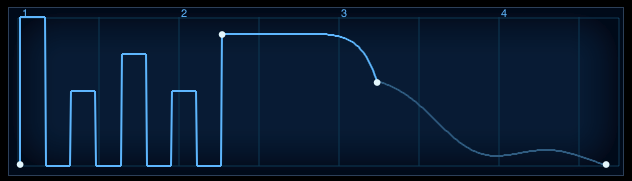
EDIT PAGE – Envelopes Editing Controls
EDIT PAGE – Envelope Editing Controls
These mode switches offer several methods for precise editing of the Envelopes.
ENVELOPES ZOOM SNAP

When SNAP is selected, any horizontal repositioning of a point is limited to 16th notes. The Envelope Display has vertical reference lines, which are helpful when using SNAP to line up the points at the 16th note divisions.
If the Envelope is short, under a few seconds, the SNAP points are correspondingly small. When an Envelope is long, the snap points appear to be greater in scale.
Keyboard Shortcut - Option/Alt
ENVELOPES ZOOM LOCK

When LOCK is enabled, all the points to the right of the point selected can be moved as one single group of stages. The only restriction is the current range of the Envelope Display.
Keyboard Shortcut -Command/Control
ENVELOPES ZOOM X/Y

This will constrain the movements vertically or horizontally.
Keyboard Shortcut - Shift
ENVELOPES ZOOM FINE

Movement of points will be at a higher resolution than normal when FINE is enabled. The numbers in the value window will be correspondingly small as long as FINE is in use.
ENVELOPES ZOOM SCALE

The range of the Envelope will be increased by dragging any of the points within it (except the first one). Scaling the Envelope beyond the limit of Envelope Display will appear to ‘squish’ many of the points together, but selecting AUTO ZOOM will expand the view to fit them all.
NOTE: When zoomed in, clicking and dragging in an empty region of the envelope display will drag the display left or right.
TIP: When modulating Pitch using Mod Envelopes, use Alt/Opt-Shift to snap points to semitones.
EDIT PAGE – Envelopes Zoom Chaos
EDIT PAGE – Envelope Chaos

The envelope contour can be randomized with the special CHAOS feature. CHAOS can change the level settings for all the points in an Envelope as well as the curve transitions between the points.
Chaos works by taking the existing points in an Envelope and randomizing their Levels and Curves based on two controls. The two sliders in the CHAOS section, CURVES and LEVELS, control the probability of randomization. Also, the four Modulation Envelopes have an automatic feature that randomizes the CHAOS on every cycle of the Envelope.
CHAOS AUTO

When enabled, the Level and Curve settings will be re-randomized with every cycle of the Envelope. For example, if an Envelope’s cycle lasts for two seconds, then every two seconds the contour will change according to the settings of the CURVES and LEVELS probability sliders.
NOTE: The AUTO switch is only available on Modulation Envelopes 1 - 4.
CHAOS SWITCH

Each time the CHAOS button is selected, it will randomize the Envelope’s contour. The two adjacent mini-sliders, CURVES and LEVELS, determine the probability of randomization made when CHAOS is selected.
NOTE: CHAOS only affects the existing points in an Envelope; it will not add or remove any stages.
CHAOS CURVES

The higher the Curves probability slider is set, the greater the likelihood of variance in the curves between the stages. Higher settings will also smooth out the sharper Envelope transition types, such as bump, pulse, spike, linear and the three and four pulses curves.
CHAOS LEVELS

The amplitude of the Envelope points will be changed more or less frequently, depending on the setting of this control. At minimum setting, the levels of the points will only change slightly. Maximum settings will produce more dramatic shifts in the Level values of the stages.
NOTE: LEVEL changes are strictly vertical; no point is moved horizontally with CHAOS.
EDIT PAGE – Envelopes Zoom Speed
EDIT PAGE – Envelopes Speed

Controls how quickly the envelope will cycle. This is a rate-based control, based on the duration of the Envelope.
For example, if the Envelope’s cycle is 2 seconds, and the SPEED slider is set to 0.50, the Envelope will take 4 seconds to complete its cycle. If the SPEED slider is set to 5.00, the Envelope will cycle 3 times every second. This control can be modulated.
Range 0.10X-10.0X (1.00X is the default)
EDIT PAGE – Envelope Zoom Velocity
EDIT PAGE – Envelope Velocity

This knob controls the effect of MIDI Velocity on the output of the envelope. Moving the slider to the left decreases the dynamic sensitivity of the envelope. Moving the slider to the right increases the sensitivity.
EDIT PAGE – Envelopes Zoom Depth
EDIT PAGE – Envelopes Depth

The Depth slider is a duplicate of the knob found on the MODS sub-page. At the minimum settings, little to no modulation will be sent to the target. At the maximum setting the full output of the Modulation Envelope will be affect the modulation target.
Range 0 to 1.00
EDIT PAGE – Envelopes Zoom Trigger
EDIT PAGE – Envelope Trigger

Several modes are available to determine how the Envelope is triggered and cycled. The NOTE/LEGATO/SONG modes are only available on the Modulation Envelopes.
LOOP

This switch toggles Envelope looping. When selected the Envelope will continually repeat.
SYNC

The Envelope will sync to the song’s tempo. Both LOOP and SYNC can be selected at the same time so the Envelope will cycle and sync to the song’s tempo.
NOTE/LEGATO/SONG

These three mode switches are only available on the Modulation Envelopes as they are related to the Modulation Envelopes Timeline display.
NOTE – With every note played, the Envelope will be retriggered.
LEGATO – The Envelope is only retriggered on the first note of a
legato passage.
SONG – The Envelope will follow the song position in the host.
EDIT PAGE – Envelopes Zoom – Zooming
EDIT PAGE – Envelopes Zoom –
Zooming
AUTO ZOOM

Selecting the button will auto-fit all of the points into the Envelope Display.
NOTE: If the Envelopes contour is very short, less than 1�4 of a bar, the Envelope Zoom will not fill the Envelope Display area with the full Envelope.
ZOOM
This slider controls the how much of the Envelope Display is seen. At the minimum value it will display a small part of the first segment and a maximum setting all 100 bars are visible.
If your mouse has a scroll wheel, you can use it to zoom. Mouse-over the envelope display and move your scroll wheel to zoom.
NOTE: If the Envelopes contour is very short, less than 1�4 of a bar, the Zoom slider will not be able to fill the Envelope Display area with the full Envelope.
EDIT PAGE - Groove Lock Envelopes
EDIT PAGE – Groove Lock™ Envelopes
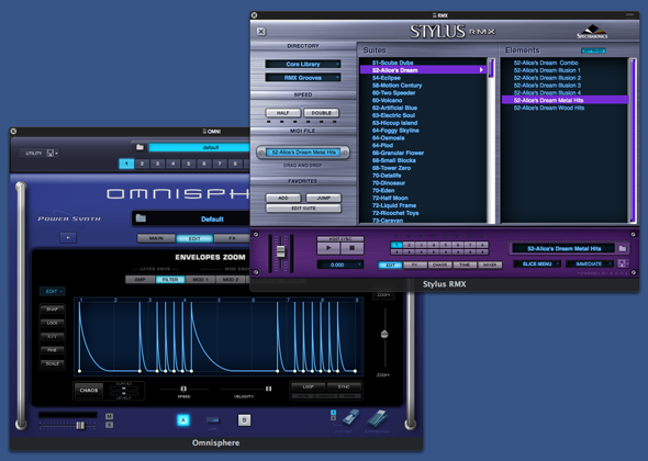
Groove Lock™ is one of Omnisphere’s most innovate features. With Groove Lock™ you can lock the groove of the Envelopes to the feel of any Stylus RMX or Standard MIDI file. This dramatically expands the rhythmic potential of the Omnisphere Envelopes. You can instantly create a Groove Lock™ envelope by simply dragging and dropping any standard MIDI file (for example, from Stylus RMX) onto the Envelope Display. This can be applied to any of the available envelope types; AMP, Filter and Mod.
When you drop a MIDI file onto the Envelope Display, it imports the rhythmic information contained in that MIDI file, resulting in a complex rhythmic envelope.
This is a very fast and convenient way to create complex envelopes, and can dramatically reduce the time required to create such envelopes from scratch.
Original ADSR Envelope
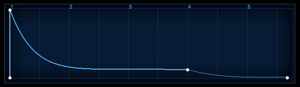
Complex Envelope after Groove Lock™applied
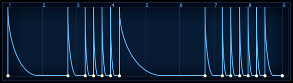
Using MIDI files provides a great starting point for creating interesting new envelopes. It allows envelopes to be Groove Locked to other Spectrasonics plug-ins, or to any MIDI-based musical phrase in your project.
HINT: When you drop a MIDI file onto the Envelope Display, it will replace the existing envelope. If desired, you can save your current envelope as an Envelope Preset before creating the new Groove Lock envelope.
EDIT PAGE – LFOS
EDIT PAGE – LFOS
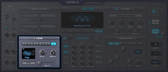
LFOs (Low Frequency Oscillators) are used for cyclical
modulation effects like vibrato, tremolo, filter sweeps and auto-pan effects.
Omnisphere has six independent LFOs available for each
Part. All six LFOs have an
identical set of parameters and can be used as sources within Omnisphere’s
Modulation Matrix.
LFO PRESETS
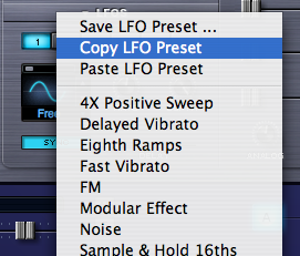
Selecting the menu arrow in the section header will display
a drop down menu that allows copying, pasting and saving of LFO settings as
presets. Below that is the list of
available LFO presets, which can be applied to the currently selected LFO. When the LFO is set up to
modulate an Omnisphere parameter, these presets can be auditioned.
LFO NUMBER

Underneath the section header are page buttons numbered 1-6,
each of which represents an LFO. Selecting a button displays the current values of that LFO’s parameters.
EDIT PAGE – LFO Waveforms
EDIT PAGE –
LFO Waveforms
Each of Omnisphere’s LFOs can have its own waveshape. There are nine available LFO
waveforms.

|
Sine – A smooth curved shape that begins positive
and then curves negative and back again. Useful for sweeps and vibrato. |
| |
|

|
Triangle – Is a positive/negative shape like the
Sine, but without curvature. Useful for sweeps and vibrato. |
| |
|

|
Square – Starts at maximum positive value and then
drops to maximum negative value. Useful for trills and pulsing effects. |
| |
|

|
Rounded Square – A smoothed Square wave. Useful for smooth pulsing. |
| |
|

|
Ramp – A linear slope from highest to lowest
value. This waveform is also
frequently referred to as a sawtooth wave. Useful for sweeps. |
| |
|

|
Reverse Ramp – A linear slope from lowest to highest
value. This waveform is also frequently referred to as an inverted sawtooth
wave. Useful for reverse sweeps |
| |
|

|
Sample and Hold – Steps through random values. Useful for classic analog synth
effects. |
| |
|

|
Heartbeat – Modeled after a human heartbeat |
| |
|

|
Noise/Random - Similar to Sample and Hold, with random
values, but doesn’t step, the values change immediately. Useful for adding chaos. |
The waveforms can be changed by selecting the stepper
buttons or by dragging the cursor on the LFO waveform display
EDIT PAGE – LFO Rate
EDIT PAGE –
LFO Rate

The Rate knob controls the speed of the LFO’s cycle.
The Rate knob has two modes. These modes depend on the state of the LFO
Sync button.
• SYNC OFF – The LFO’s rate is not synchronized with
the host tempo and the LFO’s rate is measured in Hz. The rate increases,
as it's turned clockwise.
• SYNC ON – The LFO’s rate is synchronized to the
host’s tempo. Changing the rate in Sync mode scrolls through different
rhythmic value groups - it does not simply get faster as the knob is turned
clockwise. Some examples of note values found spread out around the control
are:
8x - this value stretches a cycle across eight bars.
1/8 - this value cycles the LFO every eighth note.
1/8 dot - this value cycles the LFO every dotted eighth
note.
1/8 triplet - this value cycles the LFO every eighth note
triplet
Range (Sync Mode On)
32X, 16X, 8X, 7X, 6X, 5X, 4X, 3X, 2X,
1/1, 1/2, 1/4, 1/8, 1/16, 1/32, 1/64, 1/96,
1/1 dot, 1/2 dot, 1/4 dot, 1/8 dot, 1/16 dot,
1/1 triplet, 1/2 triplet, 1/4 triplet, 1/8 triplet, 1/16
triplet
Range (Sync Mode Off) 0 to 48Hz
EDIT PAGE – LFO Depth
EDIT PAGE –
LFO Depth

This knob controls LFO depth. The higher the setting, the greater the amount of the LFO
signal is sent to the modulation matrix.
EDIT PAGE – LFO Delay
EDIT PAGE –
LFO Delay

The Delay slider determines the how quickly the LFO’s depth
will reach its maximum strength after a note has been triggered. This allows the modulation to be
introduced gradually, for example, to achieve delayed vibrato.
When the slider is set to maximum, it will take
approximately 5 seconds for the LFO depth to reach maximum value.
The LFO Delay always works in a “legato” style trigger mode,
where subsequent legato notes do not retrigger the start of the LFO delay. The LFO Trigger Mode has no affect on
the Delay slider, since it is always in “legato” triggering mode.
EDIT PAGE - LFO Sync
EDIT PAGE - LFO
Sync

The Sync switch determines how the LFO rate behaves. When Sync is enabled, the LFO will lock
its rate to the host’s song tempo. Also, the values assigned to the Rate knob will change. Instead of displaying a value in Hz,
the values are displayed in rhythmic values.
(See the LFO Rate for the different values available when SYNC is enabled)
EDIT PAGE – LFO Trigger Mode
EDIT PAGE –
LFO Trigger Mode
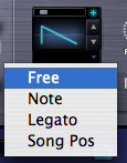
The LFO trigger mode determines how the LFO will begin its
cycle. There are four available
LFO Trigger Modes:
Free – The LFO will independently cycle regardless of when a note is
triggered.
Note – The LFO will restart its cycle with every new note that is
played.
Legato – The LFO will start its cycle when the first
note is played, but will continue its cycle when additional notes are
played. If staccato notes are
played, the LFO will restart its cycle with each note.
Song Pos – The LFO will track the bars and beats of
the song. This ‘Song Position’
mode is the best to use if repeatable results are required for playback.
EDIT PAGE – LFO Unipolar Switch
EDIT PAGE –
LFO Unipolar Switch

The Unipolar switch is represented by a small (+)
button. When it is not selected,
the LFO will be in Bipolar mode. In Bipolar mode the modulation corresponds to the mid-point of the LFO,
meaning that the LFO’s output will stay above and below the mid-point. When the Unipolar switch is selected,
the LFO is Unipolar, the LFO will above the mid-point and will double the range
of its amplitude.
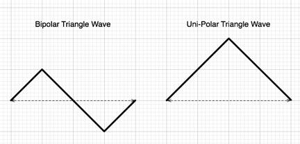
In this example, the oscillator’s pitch is being modulated
with a Sine wave from LFO1. If
LFO1 is in bipolar mode, the pitch will go above, then below, the pitch of the
note that was triggered. In
Unipolar mode, the pitch would only rise above the pitch of the note being triggered
– and the range of the change in pitch would be greater.
For example, a Unipolar LFO applied to Oscillator pitch is
great for simulating guitar-string bending, as guitarists typically bend
strings only in one direction. Another use is for a Unipolar LFO to modulate the filter-cutoff. This will often create better filter
sweeps than a bipolar LFO, as a bipolar LFO cycles below the mid-point –
so no result is heard if the cutoff frequency is low.
NOTE: If it’s desired to have
the value needs to go negative instead of positive, simply select the INVERT
button in the MODULATION section.
EDIT PAGE – LFO Phase
EDIT PAGE –
LFO Phase

The small LFO Phase slider determines the point at which the
LFO waveform will begin its cycle. If the slider is set to minimum, the LFO will begin its cycle at the
start of the waveform. As the
phase is increased, the point in the waveform that the LFO will begin its cycle
will be changed.
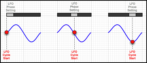
For example, if the Phase control is in the center of the
slider, the LFO will trigger from the middle of the waveform. In the screenshot above, the LFO’s
waveform is a ramp wave, and if the Phase control is in the center, the
waveform will start at the point where the slope goes below the center-point.
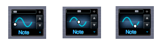
NOTE: If all six LFOs have
been routed as modulation sources, and “Modulate with LFO” is selected on any
additional parameters, they will all default to LFO1. These routings to LFO1 can be overridden in the Mod Matrix
Zoom page.